Content .. 1211 1212 1213 1214 ..
Isuzu KB P190. Manual - part 1213
7D-22 TRANSFER CASE
15. Remove the snap ring from the main shaft.
16. Use a press to remove the 2-4 hub from the main
shaft.
17. Spread the edges of the retaining ring (1) while lightly
tapping on the sun gear input shaft end. Remove the
carrier and gear assembly from the transfer case.
226R300020
18. Remove the dog teeth snap ring from the carrier and
gear assembly.
19. Remove the planetary dog teeth and the sun gear
input shaft together with the thrust needle bearing.
2260R300021
20. Remove the carrier snap ring.
21. Use a press to remove the ball bearings.
22. Use a sliding hammer (5-8840-0084-0) and a needle
bearing replacer (5-8840-0027-0) to remove the
needle bearing from the center of the carrier and gear
assembly.
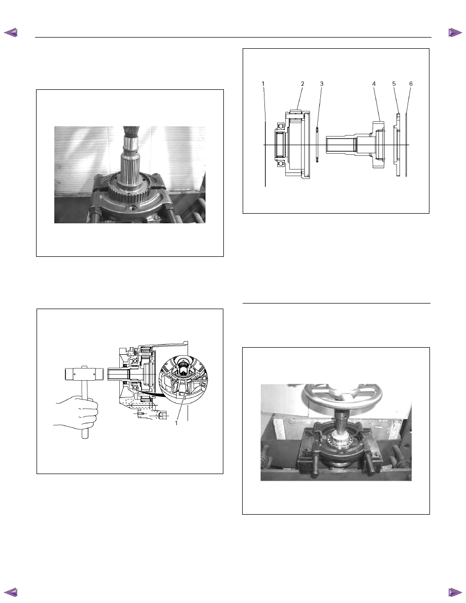
Legend
(1) Outer Retaining Ring
(2) Carrier and Gear ASM
(3) Thrust needle Bearing
(4) Sungear Input Shaft
(5) Planetary DogTeeth
(6) Dog Teeth Snap Ring