Content .. 1159 1160 1161 1162 ..
Isuzu KB P190. Manual - part 1161
7B1-38 MANUAL TRANSMISSION
Inspection and Repair
Make the necessary adjustments, repairs, and part
replacements if excessive wear or damage is
discovered during inspection.
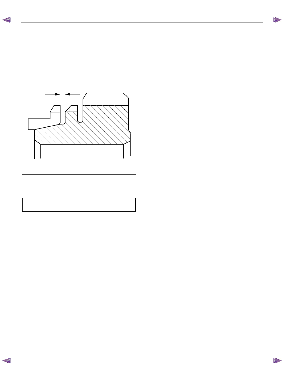
Block Ring and Dog Teeth Clearance
• Use a thickness gauge to measure the clearance
between the block ring and the dog teeth.
226RS035
If the measured value exceeds the specified limit,
the block ring must be replaced.
Block Ring and Dog Teeth Clearance
Standard Limit
1.5 mm (0.059 in)
0.8 mm (0.031 in)