Isuzu KB P190. Manual - part 1147


  Index      Isuzu     Isuzu KB P190 - service repair manual 2007 year


Search            


Content   ..  1145  1146  1147  1148   ..


Isuzu KB P190. Manual - part 1147


7B-24  MSG MODEL 


Ball bearing 

J-22912-01 


Important Operations 

1.  Top Gear Shaft Snap Ring 

2.  Top Gear Shaft 

3. Ball Bearing 

1)  Use a pair of snap ring pliers to remove the snap ring. 

2)  Use a bench press and a bearing remover to remove the 

ball bearing. 


Bearing Remover : 5-8840-0015-0 (J-22912-01) 


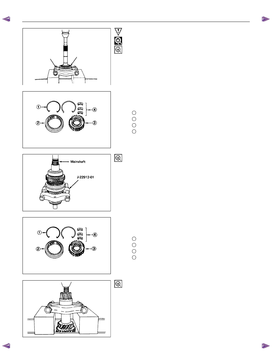
7.  3rd - 4th Synchronizer Assembly 

1)  Remove the synchronizer assembly as a set. 

2)  Disassemble the synchronizer assembly. 

1

 Springs 

2

 Sleeve 

3

 Clutch Hub 

4

 Inserts 


11. Mainshaft Ball Bearing 
Use a bench press and a bearing remover to remove the ball 
bearing. 
Bearing Remover : 5-8840-0015-0 (J-22912-01) 


17. 1st - 2nd Synchronizer Assembly 

1)  Remove the synchronizer assembly as a set. 

2)  Disassemble the synchronizer assembly. 

1

 Springs 

2

 Sleeve 

3

 Clutch Hub 

4

 Inserts 


22. Rear Ball Bearing 

24. Front Ball Bearing 
Use a bench press and a bearing remover to remove the ball 
bearing. 
Bearing Removar : 5-8840-0015-0 (J-22912-01) 
 

MSG MODEL  7B-25 

  INSPECTION AND REPAIR 

 
Make the necessary adjustments, repairs, and part replacements if excessive wear or damage is discovered during 
inspection. 


SHIFT ARM THICKNESS 

Use a micrometer to measure the shift arm thickness. 
If the measured value is less than the specified limit, the shift 
arm must be replaced. 
Shift Arm Thickness 

mm(in)


 Standard  Limit 

1st-2nd 

9.6-9.8 (0.378-0.386) 

9.0 (0.354) 

3rd-4th 

6.95-7.2 (0.274-0.283) 

6.5 (0.256) 

Rev.-5th 

6.8-6.9 (0.268-0.272) 

6.3 (0.248) 


DETENT SPRING FREE LENGTH 

Use a venier caliper to measure the detent spring free length.
If the measured value is less than the specified limit, the detent 
spring must be replaced. 
Detent Spring Free Length 

mm(in)

Standard

Limit

25.6 (1.01)

23.6 (0.93)


DETENT SPRING TENSION 

Use a spring tester to measure the valve spring tension. 
If the measured value is less than the specified limit, the valve 
spring must be replaced. 
Valve Spring Tension 

N(kg/lb)

Compressed

Height mm(in)

Standard

Limit

22.1 (0.870)

61.8-65.7

(6.3-6.7/13.9-14.8)

55.9

(5.7/12.6)


BLOCK RING AND DOG TEETH 

CLEARANCE 

Use a thickness gauge to measure the clearance between the 
block ring and the dog teeth. 
If the measured value exceeds the specified limit, the block 
ring must be replaced. 
Block Ring and Dog Teeth Clearance 

mm(in)


 Standard 

Limit 

1st,2nd 

2.0 (0.079) 

1.3 (0.051) 

3rd, 4th, 5th 

1.5 (0.059) 

0.8 (0.031) 


7B-26  MSG MODEL 


BLOCK RING AND INSERT CLEARANCE 

Use a thickness gauge to measure the clearance between the 
block ring and the insert. 
If the measured value exceeds the specified limit, the block 
ring and the insert must be replaced. 
Block Ring and Insert Clearance 

mm(in)

Standard

Limit

1st,2nd

3.46-3.74 (0.136-0.147)

3rd, 4th, 5th

3.51-3.79 (0.138-0.149)

4.0 (0.157)


CLUTCH HUB AND INSERT CLEARANCE

Use a thickness gauge to measure the clearance between the 
clutch hub and the insert. 
If the measured value exceeds the specified limit, the clutch 
hub and the insert must be replaced. 
Clutch Hub and Insert Clearance 

mm(in)

Standard

Limit

0.01 - 0.19 (0.0004 - 0.0075)

0.3 (0.012)


MAINSHAFT RUN - OUT 

1.  Install the mainshaft to a grinding machine. 

2. Use a dial indicator to measure the mainshaft central

portion run-out. 

  If the measured mainshaft run-out exceeds the specified 

limit, the mainshaft must be replaced. 

Mainshaft Run - Out 

mm(in)

Limit 

Less than 0.03 (0.0012) 


GEAR INSIDE DIAMETER 

Use an inside dial indicator to measure the gear inside 
diameter. 
If the measured value is less than the specified limit, the gear 
must be replaced. 
Gear Inside Diameter 

mm(in)

Standard

Limit

1st

Rev.

45.00-45.01

(1.7717-1.7720)

45.10 (1.7756)

2nd

3rd

41.00-41.01

(1.6142-1.6146)

41.10 (1.6181)

5th

34.03-34.04

(1.3398-1.3402)

34.10 (1.3425)


MSG MODEL  7B-27 


REVERSE IDLER GEAR AND IDLER 

GEAR SHAFT CLEARANCE 

1.  Use a micrometer to measure the idler gear shaft diameter.

2.  Use an inside dial indicator to measure the idler gear inside

diameter. 

3.  Calculate the idler gear and idler gear shaft clearance. 


Idler gear inside diameter - idler gear shaft diameter = idler 

gear and idler gear shaft clearance. 


If the measured value exceeds the specified limit, the idler

gear and/or the idler gear shaft must be replaced. 

Idler Gear and Idler Gear Shaft Clearance 

mm(in)

Standard

Limit

0.041 - 0.074 (0.0016 - 0.0029)

0.150 (0.0059)


CLUTCH HUB SPLINE PLAY 

1.  Set a dial indicator to the clutch hub to be measured. 

2.  Move the clutch hub as far as possible to both the right and

the left. 


Note the dial indicator reading. 


It the measured value exceeds the specified limit, the clutch

hub must be replaced. 

Clutch Hub Spline Play 

mm(in)


Standard Limit 

0 - 0.019 (0 - 0.0075) 

0.20 (0.0079) 


Content   ..  1145  1146  1147  1148   ..