Infiniti QX56 (JA60). Manual - part 948
TM-94
< COMPONENT DIAGNOSIS >
MAIN POWER SUPPLY AND GROUND CIRCUIT
MAIN POWER SUPPLY AND GROUND CIRCUIT
Diagnosis Procedure
INFOID:0000000005148678
1.
CHECK TCM POWER SOURCE STEP 1
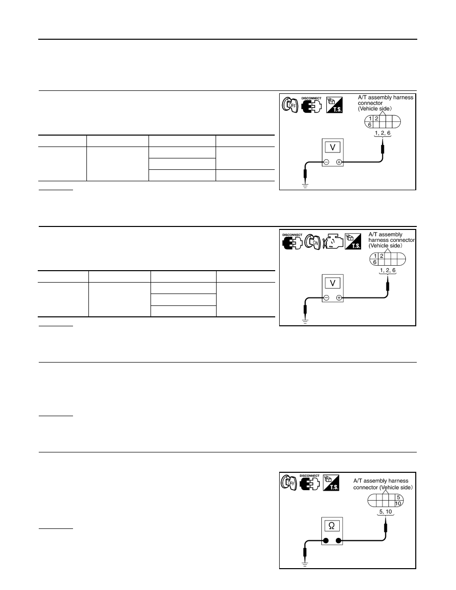
1. Turn ignition switch OFF.
2. Disconnect A/T assembly harness connector.
3. Check voltage between A/T assembly harness connector termi-
nals and ground.
OK or NG
OK
>> GO TO 2.
NG
>> GO TO 3.
2.
CHECK TCM POWER SOURCE STEP 2
1. Disconnect A/T assembly harness connector.
2. Turn ignition switch ON. (Do not start engine.)
3. Check voltage between A/T assembly harness connector termi-
nals and ground.
OK or NG
OK
>> GO TO 4.
NG
>> GO TO 3.
3.
DETECT MALFUNCTIONING ITEM
Check the following items:
• Harness for short or open between battery and A/T assembly harness connector terminals 1, 2
• Harness for short or open between ignition switch and A/T assembly harness connector terminal 6
• 10A fuse [No. 3, 4, located in the fuse block (J/B)] and 10A fuse (No. 49, located in the IPDM E/R)
• Ignition switch
OK or NG
OK
>> GO TO 4.
NG
>> Repair or replace damaged parts.
4.
CHECK TCM GROUND CIRCUIT
1. Turn ignition switch OFF.
2. Disconnect A/T assembly harness connector.
3. Check continuity between A/T assembly harness connector F9
terminals 5, 10 and ground.
If OK, check harness for short to ground and short to power.
OK or NG
OK
>> GO TO 5.
NG
>> Repair open circuit or short to ground or short to power
in harness or connectors.
Item
Connector
Terminal
Voltage
TCM
F9
1 - Ground
Battery voltage
2 - Ground
6 - Ground
0V
SCIA2104E
Item
Connector
Terminal
Voltage
TCM
F9
1 - Ground
Battery voltage
2 - Ground
6 - Ground
SCIA2105E
Continuity should exist.
SCIA2106E