Infiniti QX56 (JA60). Manual - part 949
TM-98
< COMPONENT DIAGNOSIS >
TOW MODE SWITCH
TOW MODE SWITCH
Description
INFOID:0000000005148683
When tow mode switch is “ON”, tow mode switch signals are sent to TCM from combination meter by CAN
communication line.Then it`s a tow mode condition.
Diagnosis Procedure
INFOID:0000000005148684
1.
CHECK CAN COMMUNICATION LINE
Perform the self-diagnosis. Refer to
TM-32, "CONSULT-III Function (TRANSMISSION)"
.
Is any malfunction in the CAN communication indicated in the results?
YES
>> Check CAN communication line. Refer to
.
NO
>> GO TO 2.
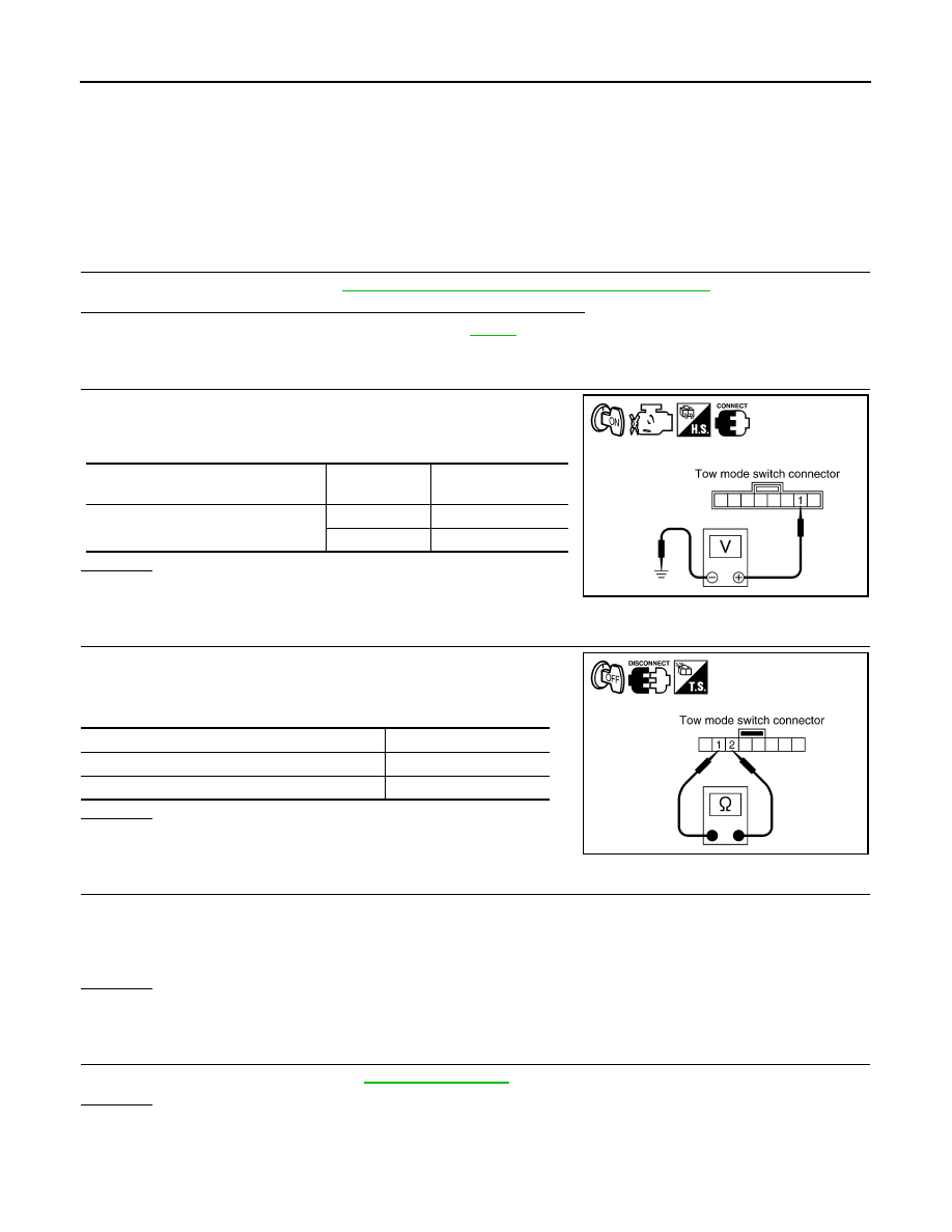
2.
CHECK POWER SOURCE
1. Turn ignition switch “ON”. (Do not start engine.)
2. Check the voltage between tow mode switch connector M258
terminal 1 and ground.
OK or NG
OK
>> INSPECTION END
NG
>> GO TO 3.
3.
CHECK TOW MODE SWITCH
1. Turn ignition switch “OFF”.
2. Disconnect tow mode switch connector.
3. Check continuity between tow mode switch terminals 1 and 2.
OK or NG
OK
>> GO TO 4.
NG
>> Repair or replace tow mode switch.
4.
DETECT MALFUNCTIONING ITEM
Check the following items. If any items are damaged, repair or replace damaged parts.
• Harness for short or open between combination meter connector terminal 35 and tow mode switch connec-
tor terminal 1.
• Harness for short or open between tow mode switch connector terminal 2 and ground.
OK or NG
OK
>> GO TO 5.
NG
>> Repair or replace damaged parts.
5.
CHECK COMBINATION METER
Check the combination meter. Refer to
OK or NG
OK
>> INSPECTION END
NO
>> Repair or replace damaged parts.
Condition
Tow mode
switch
Data (Approx.)
When ignition switch is turned to “ON”
ON
0V
OFF
Battery voltage
SCIA5156E
Condition
Continuity
Tow mode switch “ON”
Yes
Tow mode switch “OFF”
No
SCIA5584E