Infiniti QX56 (JA60). Manual - part 550


  Index      Infiniti     Infiniti QX56 (JA60) - service repair manual 2010 year


Search            


Content   ..  548  549  550  551   ..


Infiniti QX56 (JA60). Manual - part 550


FSU-6

< ON-VEHICLE MAINTENANCE >

ON-VEHICLE SERVICE

ON-VEHICLE MAINTENANCE

ON-VEHICLE SERVICE

Front Suspension Parts

INFOID:0000000005148108

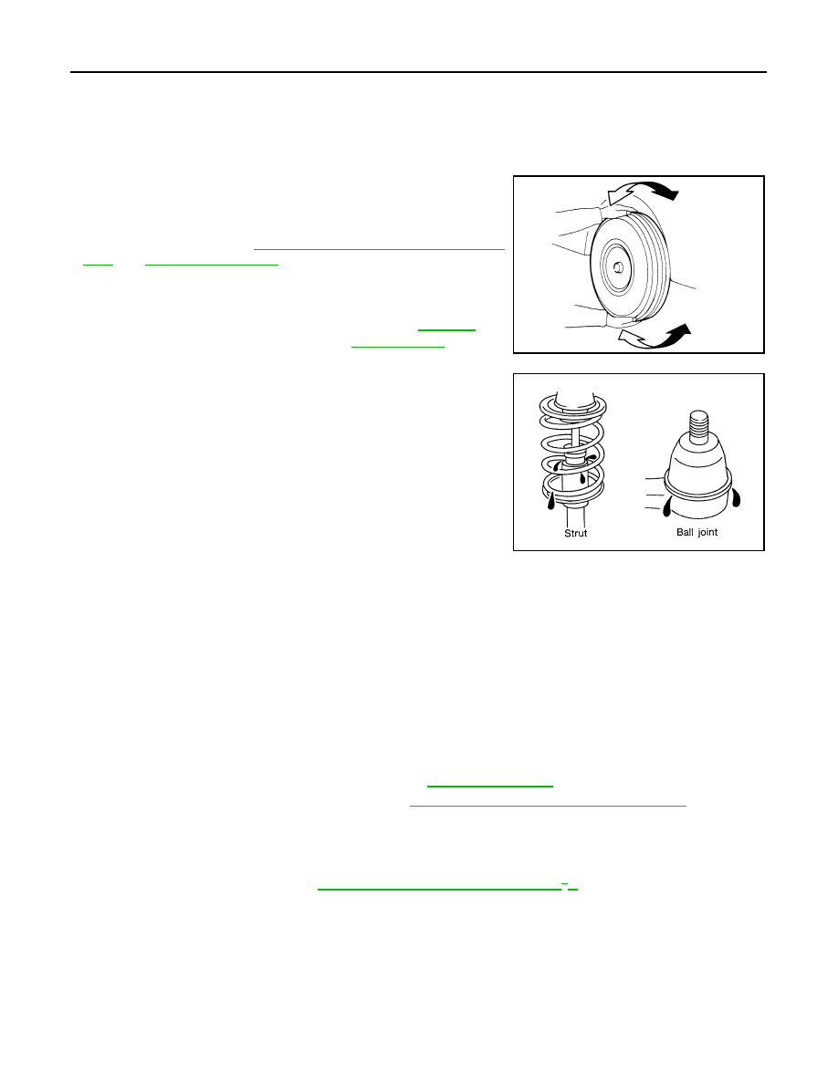
Check front suspension parts for excessive play, cracks, wear and

other damage.

• Shake each front wheel to check for excessive play.

If looseness is noted, inspect wheel bearing end play, then check

ball joint end play. Refer to 

FAX-6, "On-Vehicle Inspection and Ser-

vice"

 and 

FSU-10, "Inspection"

.

• Make sure that the cotter pin is inserted (4WD only).

• Retighten all nuts and bolts to the specified torque.

• Check shock absorber for oil leakage and other damage.

• Check suspension ball joint for grease leakage and ball joint dust

cover for cracks and other damage.

Front Wheel Alignment

INFOID:0000000005148109

PRELIMINARY INSPECTION

WARNING:

Always adjust the alignment with the vehicle on a flat surface.

NOTE:

If alignment is out of specification, inspect and replace any damaged or worn suspension parts before making

any adjustments.
1. Check and adjust the wheel alignment with the vehicle under unladen conditions. “Unladen conditions”

means that the fuel, coolant, and lubricant are full; and that the spare tire, jack, hand tools and mats are in

their designated positions.

2. Check the tires for incorrect air pressure and excessive wear.
3. Check the wheels for run out and damage. Refer to 

WT-47, "Inspection"

 .

4. Check the wheel bearing axial end play. Refer to 

FAX-6, "On-Vehicle Inspection and Service"

 .

5. Check the shock absorbers for leaks or damage.
6. Check each mounting point of the suspension components for any excessive looseness or damage.
7. Check each link, arm, and the rear suspension member for any damage.
8. Check the vehicle height. Refer to 

FSU-24, "Wheelarch Height (Unladen*

1

)"

 .

• Verify the level using Consult-III memory register 1103 and set to 0 

± 10 mm (0 ± 0.39 in) as necessary.

GENERAL INFORMATION AND RECOMMENDATIONS

1. A Four-Wheel Thrust Alignment should be performed.

• This type of alignment is recommended for any NISSAN vehicle.

• The four-wheel “thrust” process helps ensure that the vehicle is properly aligned and the steering wheel

is centered.

• The alignment machine itself should be capable of accepting any NISSAN vehicle.

• The alignment machine should be checked to ensure that it is level.

Suspension component torques : Refer to 

FSU-13, 

"Component"

 . 

SMA525A

SFA392B

ON-VEHICLE SERVICE

FSU-7

< ON-VEHICLE MAINTENANCE >

C

D

F

G

H

I

J

K

L

M

A

B

FSU

N

O

P

2. Make sure the alignment machine is properly calibrated.

• Your alignment machine should be regularly calibrated in order to give correct information.

• Check with the manufacturer of your specific alignment machine for their recommended Service/Cali-

bration Schedule.

THE ALIGNMENT PROCESS

IMPORTANT: Use only the alignment specifications listed in this Service Manual. Refer to 

FSU-23, "Wheel

Alignment (Unladen*

1

)"

 .

1. When displaying the alignment settings, many alignment machines use “indicators”: (Green/red, plus or

minus, Go/No Go). Do NOT use these indicators.

• The alignment specifications programmed into your alignment machine that operate these indicators

may not be correct.

• This may result in an ERROR.

2. Some newer alignment machines are equipped with an optional “Rolling Compensation” method to “com-

pensate” the sensors (alignment targets or head units). Do NOT use this “Rolling Compensation”

method.

• Use the “Jacking Compensation” method. After installing the alignment targets or head units, raise the

vehicle and rotate the wheels 1/2 turn both ways.

• See Instructions in the alignment machine you are using for more information.

CAMBER AND CASTER

1. Measure camber and caster of both the right and left wheels

with a suitable alignment gauge and adjust as necessary to

specification.

NOTE:

Some vehicles may be equipped with straight (non-adjustable)

lower link bolts and washers. In order to adjust camber and

caster on these vehicles, first replace the lower link bolts and

washers with adjustable (cam) bolts and washers.

2. If outside of the specified value, adjust camber and caster using

the cam bolts (1) in the front lower link (2).

CAUTION:

After adjusting the camber then check the toe-in.

NOTE:

Camber changes about 3' (0.05

°) minutes with each graduation

of one cam bolt. Refer to table below for examples of lower link

cam bolt effect on camber and caster. 

3. Tighten the adjusting bolt nuts to specification. Refer to 

FSU-13, "Component"

 .

TOE-IN

WARNING:

Camber and 
Caster

: Refer to 

FSU-23, "Wheel Alignment 

(Unladen*

1

)"

 .

SRA096A

WEIA0153E

Rear cam bolt

1 In

1 Out

1 In

1 Out

0

0

1 In

1 Out

Front cam bolt

1 Out

1 In

1 In

1 Out

1 In

1 Out

0

0

Camber
Degree minute 
(Decimal degree)

0 (0)

0 (0)

7' (0.12

°)

- 7' (-0.12

°)

3'  (0.05

°)

- 3' (-0.05

°)

3'  (0.05

°)

- 3' (-0.05

°)

Caster
Degree minute 
(Decimal degree)

- 14' (-0.23

°)

14'  (0.23

°)

0 (0)

0 (0)

7' (0.12

°)

- 7' (-0.12

°)

- 7' (-0.12

°)

7'  (0.12

°)

FSU-8

< ON-VEHICLE MAINTENANCE >

ON-VEHICLE SERVICE

• Always perform the following procedure on a flat surface.

• Make sure that no person is in front of the vehicle before pushing it.
1. Bounce the front of vehicle up and down to stabilize the vehicle height (posture).
2. Push the vehicle straight ahead about 5 m (16 ft).
3. Put a mark on base line of the tread (rear side) of both front tires

at the same height as hub center as shown. These marks are

measuring points.

4. Measure the distance (A) on the rear side of the front tires as

shown.

5. Push the vehicle slowly ahead to rotate the wheels 180

°

degrees (1/2 a turn).

CAUTION:

If the wheels have rotated more than 180

° degrees (1/2

turn), start this procedure again from the beginning. Never

push the vehicle backward.

6. Measure the distance (B) on the front side of the front tires at the

same marks as shown. Total toe-in is calculated as (A – B).

7. Adjust the toe-in by varying the length of the steering outer

socket.

a. Loosen the outer tie-rod lock nuts.
b. Adjust the toe-in by screwing the outer tie-rods in or out.

c.

Tighten the outer tie-rod lock nuts to specification.

FRONT WHEEL TURNING ANGLE

NOTE:

Check front wheel turning angle after the toe-in inspection.
1. Place front wheels on turning radius gauges in straight ahead

position and rear wheels on stands so that vehicle can be level.

Check the maximum inner and outer wheel turning angles for LH

and RH road wheels.

2. Start engine and run at idle, turn steering wheel all the way right

and left, measure the turning angle.

AFA050

Total toe-in : Refer to 

FSU-23, "Wheel Alignment (Un-

laden*

1

)"

 .

SFA234AC

Standard length (L)

Refer to 

ST-36, "Steering Outer 

Socket and Inner Socket"

 .

Lock nut 

: Refer to 

FAX-9, "Removal and In-

stallation"

 .

SGIA0167E

Wheel turning angle 
(full turn)

: Refer to 

FSU-23, "Wheel 

Alignment (Unladen*

1

)"

.

SFA439BA

ON-VEHICLE SERVICE

FSU-9

< ON-VEHICLE MAINTENANCE >

C

D

F

G

H

I

J

K

L

M

A

B

FSU

N

O

P

• Any turning angles are not adjustable. If any of steering angles are out of the specification, check if the

following parts are worn or damaged.

- Steering gear

- Steering column

- Front suspension components

If found that they are worn or damaged, replace them with new ones.


Content   ..  548  549  550  551   ..