Infiniti QX56 (JA60). Manual - part 540


  Index      Infiniti     Infiniti QX56 (JA60) - service repair manual 2010 year


Search            


Content   ..  538  539  540  541   ..


Infiniti QX56 (JA60). Manual - part 540


EXT-30

< SERVICE INFORMATION >

SIDE GUARD MOLDING

SIDE GUARD MOLDING

Removal and Installation

INFOID:0000000005147330

Removal

CAUTION:

Never apply tack-paper adhesive remover to body panel surface finished with lacquer-based paints.

• Original side guard molding is affixed to body panel with double-faced adhesive tape and plastic clips.
1. Heat side guard molding to between 30

° and 40°C (86° to 104°F) with a heat gun.

2. Raise end of side guard molding, cut away double-faced adhesive tape and release clips to remove side

guard molding. 

• Remove all traces of double-faced adhesive tape.

Installation

• On vehicles coated with Hard Clear Coat, use double-faced 3M adhesive tape Product No. 4210 or equiva-

lent, after priming with 3M primer Product No. N200, C-100 or equivalent. 

• The repair parts are also affixed with double-faced adhesive tape.

• To re-use existing side guard molding, clean all traces of double-faced adhesive tape from the side guard

molding and apply new double-faced adhesive tape to the side guard molding.

1. Clean the panel surface with isopropyl alcohol or equivalent to degrease the surface.
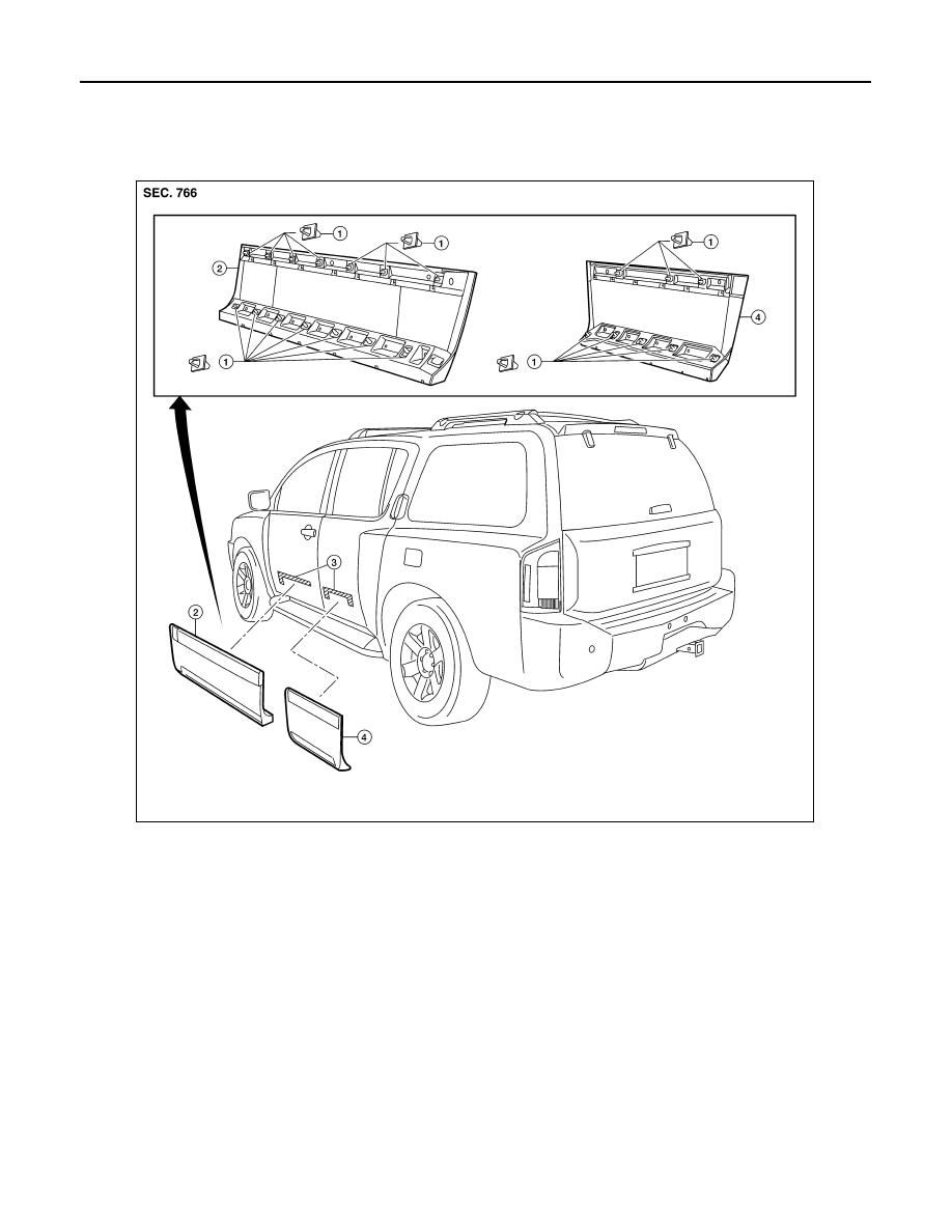
1.

Clip C103

2.

Front door side guard molding

3.

Double-faced adhesive tape

4.

Rear door side guard molding

BIIA0017E

SIDE GUARD MOLDING

EXT-31

< SERVICE INFORMATION >

C

D

E

F

G

H

I

J

L

M

A

B

EXT

N

O

P

2. Heat the panel and double-faced adhesive tape surface to 30

° to 40°C (86° to 104°F).

3. Remove the backing sheet from the double-faced adhesive tape surface.

• Align the plastic clips into the holes in the outer door.

• Continue aligning the plastic clips into their corresponding holes in the outer door during installation.

4. Press ends by hand and use a roller to apply 5 kg-f (11 lbs-f) to press double-faced adhesive tape surface

on side guard molding to door surface.

• Apply even pressure along double-faced adhesive tape surface on side guard molding to insure proper

wet out.

CAUTION:

To secure contact of double-faced adhesive tape, do not wash vehicle for 24 hours after installation.

FAX-1

TRANSMISSION & DRIVELINE

C

E

F

G

H

I

J

K

L

M

SECTION 

FAX

A

B

FAX

N

O

P

CONTENTS

FRONT AXLE

PRECAUTION ...............................................

2

PRECAUTIONS ...................................................

2

Precaution for Supplemental Restraint System 
(SRS) "AIR BAG" and "SEAT BELT PRE-TEN-
SIONER" .................................................................
..

2

Precaution Necessary for Steering Wheel Rota-
tion After Battery Disconnect ...................................
..

2

Precaution .................................................................

3

PREPARATION ............................................

4

PREPARATION ...................................................

4

Special Service Tool  .................................................

4

Commercial Service Tool  ..........................................

4

SYMPTOM DIAGNOSIS  ...............................

5

NOISE, VIBRATION AND HARSHNESS 
(NVH) TROUBLESHOOTING  .............................

5

NVH Troubleshooting Chart  ......................................

5

ON-VEHICLE MAINTENANCE .....................

6

WHEEL HUB  ......................................................

6

On-Vehicle Inspection and Service  ..........................

6

REMOVAL AND INSTALLATION ................

7

WHEEL HUB  ......................................................

7

Removal and Installation  ..........................................

7

DRIVE SHAFT ....................................................

9

Removal and Installation  ..........................................

9

DISASSEMBLY AND ASSEMBLY ..............

11

DRIVE SHAFT ...................................................

11

Disassembly and Assembly .....................................

11

SERVICE DATA AND SPECIFICATIONS 
(SDS) ............................................................

16

SERVICE DATA AND SPECIFICATIONS 
(SDS) .................................................................

16

Wheel Bearing  .........................................................

16

Drive Shaft ...............................................................

16

Boot Bands  ..............................................................

16

FAX-2

< PRECAUTION >

PRECAUTIONS

PRECAUTION

PRECAUTIONS

Precaution for Supplemental Restraint System (SRS) "AIR BAG" and "SEAT BELT 
PRE-TENSIONER"

INFOID:0000000005266468

The Supplemental Restraint System such as “AIR BAG” and “SEAT BELT PRE-TENSIONER”, used along

with a front seat belt, helps to reduce the risk or severity of injury to the driver and front passenger for certain

types of collision. This system includes seat belt switch inputs and dual stage front air bag modules. The SRS

system uses the seat belt switches to determine the front air bag deployment, and may only deploy one front

air bag, depending on the severity of a collision and whether the front occupants are belted or unbelted.

Information necessary to service the system safely is included in the SR and SB section of this Service Man-

ual.

WARNING:

• To avoid rendering the SRS inoperative, which could increase the risk of personal injury or death in

the event of a collision which would result in air bag inflation, all maintenance must be performed by

an authorized NISSAN/INFINITI dealer.

• Improper maintenance, including incorrect removal and installation of the SRS, can lead to personal

injury caused by unintentional activation of the system. For removal of Spiral Cable and Air Bag

Module, see the SR section.

• Do not use electrical test equipment on any circuit related to the SRS unless instructed to in this

Service Manual. SRS wiring harnesses can be identified by yellow and/or orange harnesses or har-

ness connectors.

PRECAUTIONS WHEN USING POWER TOOLS (AIR OR ELECTRIC) AND HAMMERS

WARNING:

• When working near the Airbag Diagnosis Sensor Unit or other Airbag System sensors with the Igni-

tion ON or engine running, DO NOT use air or electric power tools or strike near the sensor(s) with a

hammer. Heavy vibration could activate the sensor(s) and deploy the air bag(s), possibly causing

serious injury.

• When using air or electric power tools or hammers, always switch the Ignition OFF, disconnect the

battery, and wait at least 3 minutes before performing any service.

Precaution Necessary for Steering Wheel Rotation After Battery Disconnect

INFOID:0000000005266469

NOTE:

• This Procedure is applied only to models with Intelligent Key system and NATS (NISSAN ANTI-THEFT SYS-

TEM).

• Remove and install all control units after disconnecting both battery cables with the ignition knob in the

″LOCK″ position.

• Always use CONSULT-III to perform self-diagnosis as a part of each function inspection after finishing work.

If DTC is detected, perform trouble diagnosis according to self-diagnostic results.

For models equipped with the Intelligent Key system and NATS, an electrically controlled steering lock mech-

anism is adopted on the key cylinder.

For this reason, if the battery is disconnected or if the battery is discharged, the steering wheel will lock and

steering wheel rotation will become impossible.

If steering wheel rotation is required when battery power is interrupted, follow the procedure below before

starting the repair operation.

OPERATION PROCEDURE

1. Connect both battery cables.

NOTE:

Supply power using jumper cables if battery is discharged.

2. Use the Intelligent Key or mechanical key to turn the ignition switch to the 

″ACC″ position. At this time, the

steering lock will be released.

3. Disconnect both battery cables. The steering lock will remain released and the steering wheel can be

rotated.

4. Perform the necessary repair operation.


Content   ..  538  539  540  541   ..