Infiniti QX56 (JA60). Manual - part 314


  Index      Infiniti     Infiniti QX56 (JA60) - service repair manual 2010 year


Search            


Content   ..  312  313  314  315   ..


Infiniti QX56 (JA60). Manual - part 314


SERVICE DATA AND SPECIFICATIONS (SDS)

DLN-179

< SERVICE DATA AND SPECIFICATIONS (SDS) 

[ATX14B]

C

E

F

G

H

I

J

K

L

M

A

B

DLN

N

O

P

SERVICE DATA AND SPECIFICATIONS (SDS)

SERVICE DATA AND SPECIFICATIONS (SDS)

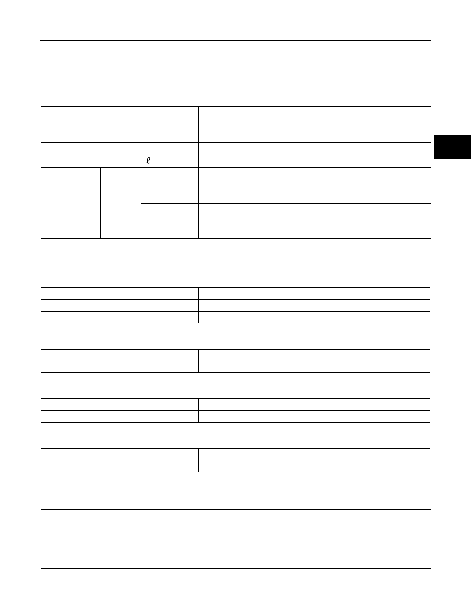
General Specification

INFOID:0000000005148896

Inspection and Adjustment

INFOID:0000000005148897

CLEARANCE BETWEEN INNER GEAR AND OUTER GEAR

Unit: mm (in)

CLUTCH

Unit: mm (in)

PINION GEAR END PLAY

Unit: mm (in)

CLEARANCE BETWEEN SHIFT FORK AND SLEEVE

Unit: mm (in)

SELECTIVE PARTS

Sub-oil Pump

Unit: mm (in)

*: Always check with the Parts Department for the latest parts information.

Applied model

4WD

VK56DE

A/T

Transfer model

ATX14B

Fluid capacity (Approx.)

 (US qt, lmp qt)

3.0 (3-1/8, 2-5/8)

Gear ratio

High

1.000

Low

2.625

Number of teeth

Planetary 
gear

Sun gear

57

Internal gear

91

Front drive sprocket

38

Front drive shaft

38

Item

Specification

Sub-oil pump

0.015 - 0.035 (0.0006 - 0.0014)

Main oil pump

0.015 - 0.035 (0.0006 - 0.0014)

Item

Limit value

Drive plate

1.4 (0.055)

Item

Standard

Pinion gear end play

0.1 - 0.7 (0.004 - 0.028)

Item

Standard

Shift fork and sleeve

Less than 0.36 (0.0142)

Gear thickness

Part number*

Inner gear

Outer gear

9.27 - 9.28 (0.3650 - 0.3654)

31346 0W462

31347 0W462

9.28 - 9.29 (0.3654 - 0.3657)

31346 0W461

31347 0W461

9.29 - 9.30 (0.3657 - 0.3661)

31346 0W460

31347 0W460

DLN-180

< SERVICE DATA AND SPECIFICATIONS (SDS) 

[ATX14B]

SERVICE DATA AND SPECIFICATIONS (SDS)

Main Oil Pump

Unit: mm (in)

*: Always check with the Parts Department for the latest parts information.

Control Valve

Unit: mm (in)

*: Always check with the Parts Department for the latest parts information.

Control Valve Spring

Unit: mm (in)

*: Always check with the Parts Department for the latest parts information.

Return Spring

Unit: mm (in)

*: Always check with the Parts Department for the latest parts information.

Gear thickness

Part number*

Inner gear

Outer gear

8.27 - 8.28 (0.3256 - 0.3260)

31346 7S112

31347 7S112

8.28 - 8.29 (0.3260 - 0.3264)

31346 7S111

31347 7S111

8.29 - 8.30 (0.3264 - 0.3268)

31346 7S110

31347 7S110

Mounting position

(Part name)

Part number*

Outer dia.

Overall length

L1

(2-4 shift valve)

31772 21X00

8.0 (0.315)

38.5 (1.516)

L2

(Clutch valve)

31772 80X11

10.0 (0.394)

40.0 (1.575)

L4

(Pilot valve)

31772 80X11

10.0 (0.394)

40.0 (1.575)

L5

(Regulator valve)

31741 0W410

12.0 (0.472)

68.0 (2.677)

Mounting position

(Part name)

Part number*

Free length

Outer dia.

Overall length

L1

(2-4 shift valve spring)

31742 2W500

31.85 (1.2539)

7.0 (0.276)

0.6 (0.024)

L2

(Clutch valve spring)

31742 2W505

40.6 (1.598)

8.9 (0.350)

0.7 (0.028)

L4

(Pilot valve spring)

31742 0W410

28.1 (1.106)

9.0 (0.354)

1.2 (0.047)

L5

(Regulator valve spring)

31742 2W515

39.7 (1.563)

11.0 (0.433)

1.3 (0.051)

Stamped mark

Part number*

Free length

1

31521 7S111

42.7 (1.168)

2

31521 7S112

43.1 (1.697)

3

31521 7S113

43.6 (1.717)

4

31521 7S114

44.0 (1.731)

PRECAUTIONS

DLN-181

< PRECAUTION >

[PROPELLER SHAFT: 2F1310]

C

E

F

G

H

I

J

K

L

M

A

B

DLN

N

O

P

PRECAUTION

PRECAUTIONS

Precaution for Supplemental Restraint System (SRS) "AIR BAG" and "SEAT BELT 
PRE-TENSIONER"

INFOID:0000000005335152

The Supplemental Restraint System such as “AIR BAG” and “SEAT BELT PRE-TENSIONER”, used along

with a front seat belt, helps to reduce the risk or severity of injury to the driver and front passenger for certain

types of collision. This system includes seat belt switch inputs and dual stage front air bag modules. The SRS

system uses the seat belt switches to determine the front air bag deployment, and may only deploy one front

air bag, depending on the severity of a collision and whether the front occupants are belted or unbelted.

Information necessary to service the system safely is included in the SR and SB section of this Service Man-

ual.

WARNING:

• To avoid rendering the SRS inoperative, which could increase the risk of personal injury or death in

the event of a collision which would result in air bag inflation, all maintenance must be performed by

an authorized NISSAN/INFINITI dealer.

• Improper maintenance, including incorrect removal and installation of the SRS, can lead to personal

injury caused by unintentional activation of the system. For removal of Spiral Cable and Air Bag

Module, see the SR section.

• Do not use electrical test equipment on any circuit related to the SRS unless instructed to in this

Service Manual. SRS wiring harnesses can be identified by yellow and/or orange harnesses or har-

ness connectors.

PRECAUTIONS WHEN USING POWER TOOLS (AIR OR ELECTRIC) AND HAMMERS

WARNING:

• When working near the Airbag Diagnosis Sensor Unit or other Airbag System sensors with the Igni-

tion ON or engine running, DO NOT use air or electric power tools or strike near the sensor(s) with a

hammer. Heavy vibration could activate the sensor(s) and deploy the air bag(s), possibly causing

serious injury.

• When using air or electric power tools or hammers, always switch the Ignition OFF, disconnect the

battery, and wait at least 3 minutes before performing any service.

Precaution Necessary for Steering Wheel Rotation After Battery Disconnect

INFOID:0000000005335151

NOTE:

• This Procedure is applied only to models with Intelligent Key system and NATS (NISSAN ANTI-THEFT SYS-

TEM).

• Remove and install all control units after disconnecting both battery cables with the ignition knob in the

″LOCK″ position.

• Always use CONSULT-III to perform self-diagnosis as a part of each function inspection after finishing work.

If DTC is detected, perform trouble diagnosis according to self-diagnostic results.

For models equipped with the Intelligent Key system and NATS, an electrically controlled steering lock mech-

anism is adopted on the key cylinder.

For this reason, if the battery is disconnected or if the battery is discharged, the steering wheel will lock and

steering wheel rotation will become impossible.

If steering wheel rotation is required when battery power is interrupted, follow the procedure below before

starting the repair operation.

OPERATION PROCEDURE

1. Connect both battery cables.

NOTE:

Supply power using jumper cables if battery is discharged.

2. Use the Intelligent Key or mechanical key to turn the ignition switch to the 

″ACC″ position. At this time, the

steering lock will be released.

3. Disconnect both battery cables. The steering lock will remain released and the steering wheel can be

rotated.

4. Perform the necessary repair operation.

DLN-182

< PRECAUTION >

[PROPELLER SHAFT: 2F1310]

PRECAUTIONS

5. When the repair work is completed, return the ignition switch to the 

″LOCK″ position before connecting

the battery cables. (At this time, the steering lock mechanism will engage.)

6. Perform a self-diagnosis check of all control units using CONSULT-III. 


Content   ..  312  313  314  315   ..