Infiniti QX56 (Z62). Manual - part 645
EM-20
< PERIODIC MAINTENANCE >
DRIVE BELTS
PERIODIC MAINTENANCE
DRIVE BELTS
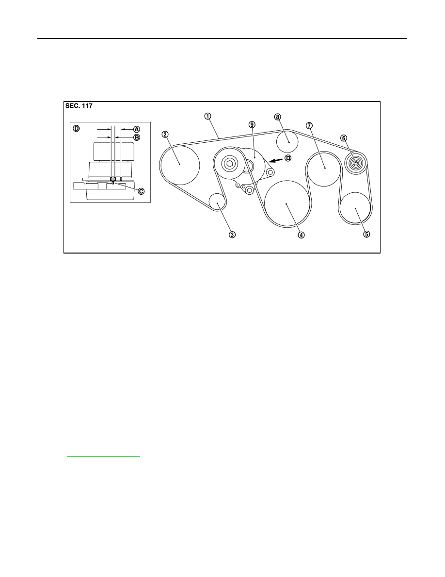
Exploded View
INFOID:0000000006289524
Checking
INFOID:0000000006289525
WARNING:
Be sure to perform the these steps when engine is stopped.
• Check that the indicator (C) (notch on fixed side) of each auto-tensioner is within the possible use range (A).
NOTE:
• Check the each auto-tensioners indication when the engine is cold.
• When new drive belts is installed, the indicator (notch on fixed side) should be within the range (B) in the
figure.
• Visually check all drive belts for wear, damage or cracks.
• If the indicator (notch on fixed side) is out of the possible use range or drive belts are damaged, replace drive
belts.
Tension Adjustment
INFOID:0000000006289526
Removal and Installation
INFOID:0000000006289527
REMOVAL
1.
Move reservoir tank to the position without the hindrance for work. Refer to
.
1.
Drive belt
2.
Power steering oil pump pulley
3.
Alternator pulley
4.
Crankshaft pulley
5.
A/C compressor
6.
Idler pulley
7.
Cooling fan pulley
8.
Water pump pulley
9.
Drive belt auto-tensioner
A.
Possible use range
B.
Range when new drive belt is in-
stalled
C.
Indicator
D.
View D
JPBIA3264ZZ