Infiniti QX56 (Z62). Manual - part 643


  Index      Infiniti     Infiniti QX56 (Z62) - service repair manual 2011 year


Search            


Content   ..  641  642  643  644   ..


Infiniti QX56 (Z62). Manual - part 643


EM-12

< BASIC INSPECTION >

CAMSHAFT VALVE CLEARANCE

BASIC INSPECTION

CAMSHAFT VALVE CLEARANCE

Inspection

INFOID:0000000006289520

INSPECTION

Check valve clearance if applicable to the following cases:

Intake side:

• At the removal and installation of VVEL ladder assembly or valve-related parts, or at the occurrence of mal-

function (poor starting, idle malfunction, unusual noise) due to aged deterioration in valve clearance.

CAUTION:

Valve clearance check on the intake side is not required after replacing the VVEL ladder assembly &
cylinder head assembly with a new one. (Install new VVEL ladder assembly & cylinder head assembly
in factory-shipped condition because it is factory-adjusted and inspected.)
NOTE:
VVEL ladder assembly cannot be replaced as a single part, because it is machined together with cylinder
head assembly.

Exhaust side:

• At the removal, installation, and replacement of exhaust camshaft or valve-related parts, or at the occur-

rence of malfunction (poor starting, idle malfunction, unusual noise) due to aged deterioration in valve clear-
ance.

1.

Remove VVEL actuator motor assembly. Refer to 

EM-36, "Removal and Installation"

.

2.

Remove rocker covers (bank 1 and bank 2). Refer to 

EM-33, "Removal and Installation"

.

3.

Remove VVEL actuator housing assembly. Refer to 

EM-36, "Removal and Installation"

.

4.

Measure the valve clearance as per the following:
• Use the feeler gauge (commercial service tool) of curved-tip. This allows the feeler gauge to access the

clearance between camshaft (drive shaft) nose and valve lifter with ease.

NOTE:
Be sure to note the following points when measuring valve clearance on the intake side.
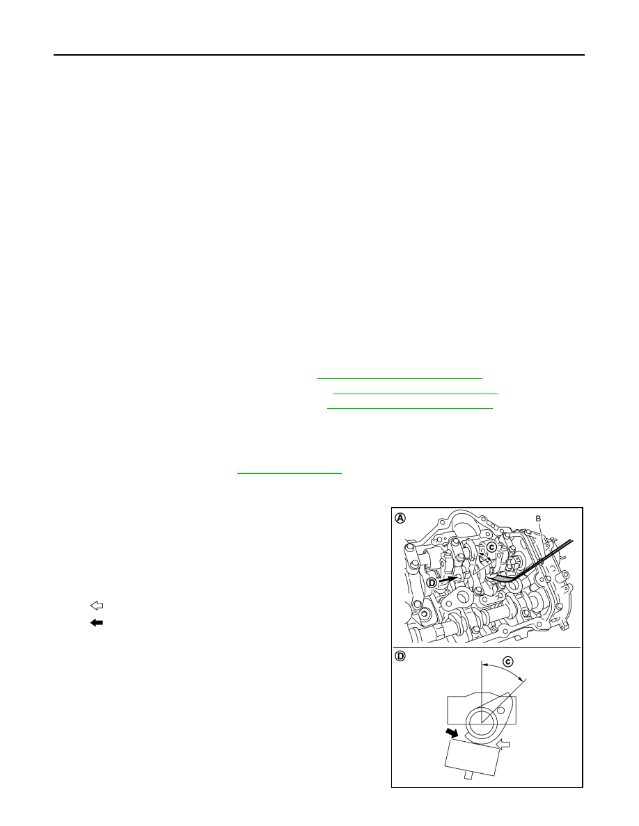
• Before measuring, check that the position of drive shaft nose

is within the angle shown in the figure.

• Refer to the figure for the insertion direction of the feeler

gauge since the direction depends on the bank.

Valve clearance

: Refer to 

EM-133, "Camshaft"

.

A

:  Bank  2

B

: Feeler gauge (commercial service tool)

c

: 45 degrees (drive shaft nose angle)

D

:  View  D

: Insertion direction of feeler gauge on the bank 2

: Insertion direction of feeler gauge on the bank 1

JPBIA3485ZZ

CAMSHAFT VALVE CLEARANCE

EM-13

< BASIC INSPECTION >

C

D

E

F

G

H

I

J

K

L

M

A

EM

N

P

O

a.

Set No. 1 cylinder at TDC of its compression stroke.
• Rotate crankshaft pulley clockwise to align timing mark

(grooved line without color) (B) with timing indicator (A).

• Check that exhaust cam nose on No. 1 cylinder (engine front

side of bank 1) is located as shown in the figure.

• If not, turn crankshaft one revolution (360 degrees) and align

as shown in the figure.

• By referring to the figure, measure the valve clearances at

locations marked “

×

” as shown in the table below (locations

indicated in the figure).

• No. 1 cylinder at compression TDC

NOTE:

JPBIA2070ZZ

1

: Exhaust camshaft (bank 1)

: Engine front

JPBIA2071ZZ

: Engine front

Measuring position [bank 2 (A)]

No. 2 

CYL.

No. 4 

CYL. 

No. 6 

CYL.

No. 8 

CYL.

No. 1 cylinder at com-

pression TDC

EXH

×

 (C)

INT

×

 (D)

×

 (E)

Measuring position [bank 1 (B)]

No. 1 

CYL.

No. 3 

CYL.

No. 5 

CYL.

No. 7 

CYL.

No. 1 cylinder at com-

pression TDC

INT

×

 (F)

×

 (G)

EXH

×

 (H)

×

 (I)

JPBIA3488ZZ

EM-14

< BASIC INSPECTION >

CAMSHAFT VALVE CLEARANCE

To measure valve clearance of No. 1 cylinder INT valve (front
side), insert feeler gauge (A) (commercial service tool) as shown
in the figure.

b.

Rotate crankshaft 270 degrees clockwise (when viewed from engine front) to align No. 3 cylinder at TDC
its compression stroke.
NOTE:
Crankshaft pulley mounting bolt flange has an angle mark (B)
every 90 degrees (c). They can be used as a guide to rotation
angle. 

• By referring to the figure, measure the valve clearances at

locations marked “

×

” as shown in the table below (locations

indicated in the figure).

• No. 3 cylinder at compression TDC

c.

Rotate crankshaft 90 degrees clockwise (when viewed from engine front) to align No. 6 cylinder at TDC of
compression stroke.
NOTE:

: Engine front

JPBIA3489ZZ

A

: Paint mark

JPBIA2066ZZ

: Engine front

Measuring position [bank 2 (A)]

No. 2 

CYL.

No. 4 

CYL. 

No. 6 

CYL.

No. 8 

CYL.

No. 3 cylinder at com-

pression TDC

EXH

×

 (C)

INT

×

 (D)

Measuring position [bank 1 (B)]

No. 1 

CYL.

No. 3 

CYL.

No. 5 

CYL.

No. 7 

CYL.

No. 3 cylinder at com-

pression TDC

INT

×

 (E)

×

 (F)

EXH

×

 (G)

×

 (H)

JPBIA3490ZZ

CAMSHAFT VALVE CLEARANCE

EM-15

< BASIC INSPECTION >

C

D

E

F

G

H

I

J

K

L

M

A

EM

N

P

O

Crankshaft pulley mounting bolt flange has an angle mark (B)
every 90 degrees (c). They can be used as a guide to rotation
angle. 

• By referring to the figure, measure the valve clearances at

locations marked “

×

” as shown in the table below (locations

indicated in the figure).

• No. 6 cylinder at compression TDC

5.

Perform adjustment or replacement if the measured value is out of the standard. 
• If a valve clearance on the exhaust side is out of specification, adjust the valve clearance. Refer to 

EM-

77, "Inspection"

.

• If a valve clearance on the intake side is out of specification, replace VVEL ladder assembly & cylinder

head assembly. Refer to 

EM-86, "Exploded View"

.

CAUTION:

Never adjust valve clearance on the intake side.
NOTE:
Since the valve lifter (INT) cannot be replaced by the piece, VVEL ladder assembly & cylinder head
assembly replacement are required.

A

: Paint mark

JPBIA2066ZZ

: Engine front

Measuring position [bank 2 (A)]

No. 2 

CYL.

No. 4 

CYL. 

No. 6 

CYL.

No. 8 

CYL.

No. 6 cylinder at com-

pression TDC

EXH

×

 (B)

×

 (C)

INT

×

 (D)

JPBIA3491ZZ


Content   ..  641  642  643  644   ..