Infiniti QX56 (Z62). Manual - part 36
SEAT MEMORY SWITCH
ADP-137
< REMOVAL AND INSTALLATION >
C
D
E
F
G
H
I
K
L
M
A
B
ADP
N
O
P
SEAT MEMORY SWITCH
Removal and Installation
INFOID:0000000006248443
REMOVAL
CAUTION:
When removing and installing, use shop cloths to protect parts from damage.
1.
Remove front door garnish (1). Refer to
.
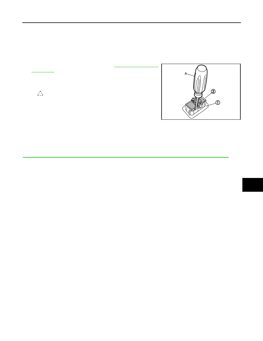
2.
Press pawls and remove seat memory switch (2) from front door
garnish (1), with flat-bladed screw driver (A).
INSTALLATION
Install in the reverse order of removal.
CAUTION:
Be sure to clump the harness to the right place.
NOTE:
After installing the driver seat, perform additional service when removing battery negative terminal. Refer to
ADP-51, "ADDITIONAL SERVICE WHEN REMOVING BATTERY NEGATIVE TERMINAL : Description"
:
Pawl
JMJIA1817ZZ