Infiniti QX4 (R50). Manual - part 528
SRS949
SRS164
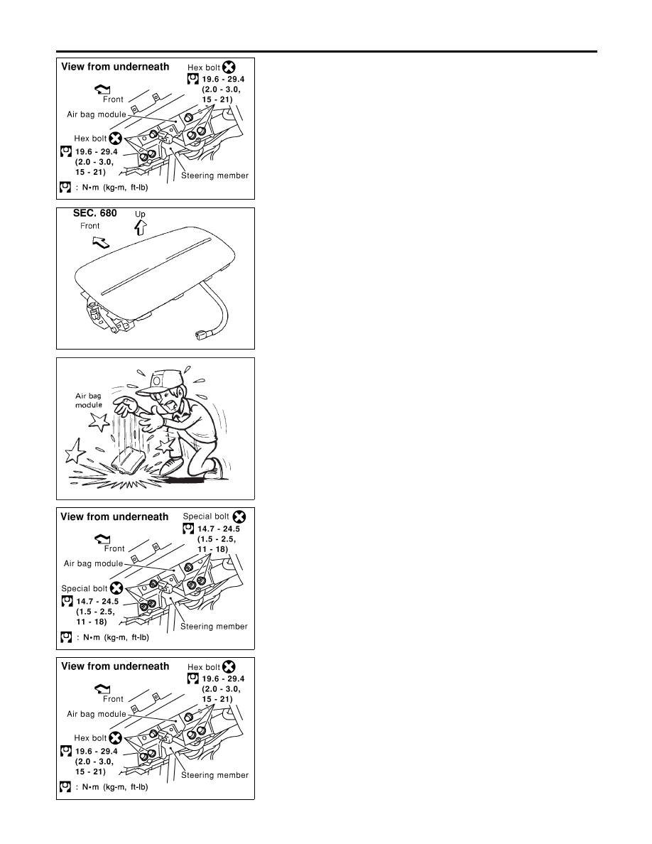
CAUTION:
I
Always place air bag module with pad side facing upward.
I
Do not attempt to disassemble air bag module.
I
The special bolts are coated with bonding agent. Do not
use old bolts after removal; replace with new coated bolts.
I
Do not insert any foreign objects (screwdriver, etc.) into
air bag module connector.
SBF814E
I
Replace air bag module if it has been dropped or sus-
tained an impact.
I
Do not expose the air bag module to temperatures exceed-
ing 90°C (194°F).
I
Do not allow oil, grease or water to come in contact with
the air bag module.
I
After air bag inflates, the front instrument panel assembly
should be replaced if damaged.
SRS948
INSTALLATION
NBRS0017
CAUTION:
I
Always work from the side of or under air bag module.
1.
Install front passenger air bag module to instrument panel
assembly.
2.
Install instrument panel.
I
Ensure harness is not caught between rear of air bag module
and steering member.
3.
Install front passenger air bag module to steering member.
SRS949
SUPPLEMENTAL RESTRAINT SYSTEM (SRS)
Front Passenger Air Bag Module (Cont’d)
RS-20