Infiniti QX4 (R50). Manual - part 213
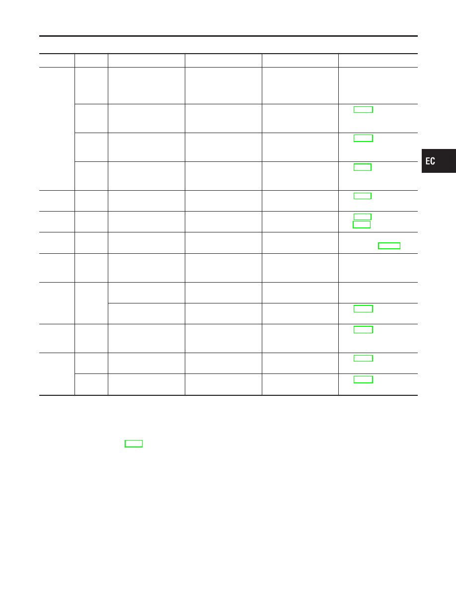
Main 12 Causes of Overheating
NBEC0615
Engine
Step
Inspection item
Equipment
Standard
Reference page
OFF
1
I
Blocked radiator
I
Blocked condenser
I
Blocked radiator grille
I
Blocked bumper
I
Visual
No blocking
—
2
I
Coolant mixture
I
Coolant tester
50 - 50% coolant mixture See MA-11, “RECOM-
MENDED FLUIDS AND
LUBRICANTS”.
3
I
Coolant level
I
Visual
Coolant up to MAX level
in reservoir tank and
radiator filler neck
See MA-14, “Changing
Engine Coolant”.
4
I
Radiator cap
I
Pressure tester
59 - 98 kPa
(0.6 - 1.0 kg/cm
2
, 9 - 14
psi) (Limit)
See LC-11, “System
Check”.
ON*
2
5
I
Coolant leaks
I
Visual
No leaks
See LC-11, “System
Check”.
ON*
2
6
I
Thermostat
I
Touch the upper and
lower radiator hoses
Both hoses should be
hot
See LC-16, “Thermostat”
and LC-19, “Radiator”.
ON*
1
7*
5
I
Cooling fan
I
CONSULT-II
Operating
See trouble diagnosis for
DTC P0217 (EC-314).
OFF
8
I
Combustion gas leak
I
Color checker chemi-
cal tester 4 Gas ana-
lyzer
Negative
—
ON*
3
9
I
Coolant temperature
gauge
I
Visual
Gauge less than 3/4
when driving
—
I
Coolant overflow to
reservoir tank
I
Visual
No overflow during driv-
ing and idling
See MA-14, “Changing
Engine Coolant”.
OFF*
4
10
I
Coolant return from
reservoir tank to radia-
tor
I
Visual
Should be initial level in
reservoir tank
See MA-13, “ENGINE
MAINTENANCE”.
OFF
11
I
Cylinder head
I
Straight gauge feeler
gauge
0.1 mm (0.004 in) Maxi-
mum distortion (warping)
See EM-42, “Inspection”.
12
I
Cylinder block and pis-
tons
I
Visual
No scuffing on cylinder
walls or piston
See EM-63, “Inspection”.
*1: Turn the ignition switch ON.
*2: Engine running at 3,000 rpm for 10 minutes.
*3: Drive at 90 km/h (55 MPH) for 30 minutes and then let idle for 10 minutes.
*4: After 60 minutes of cool down time.
*5: Cooling fan is not applied to this vehicle.
For more information, refer to LC-24, “OVERHEATING CAUSE ANALYSIS”.
GI
MA
EM
LC
FE
AT
TF
PD
AX
SU
BR
ST
RS
BT
HA
SC
EL
IDX
DTC P0217 COOLANT OVERTEMPERATURE ENRICHMENT PROTECTION
Main 12 Causes of Overheating
EC-319