Infiniti QX4 (R50). Manual - part 153


  Index      Infiniti     Infiniti QX4 (R50) - service repair manual 2001 year


Search            copyright infringement  


Content   ..  151  152  153  154   ..


Infiniti QX4 (R50). Manual - part 153


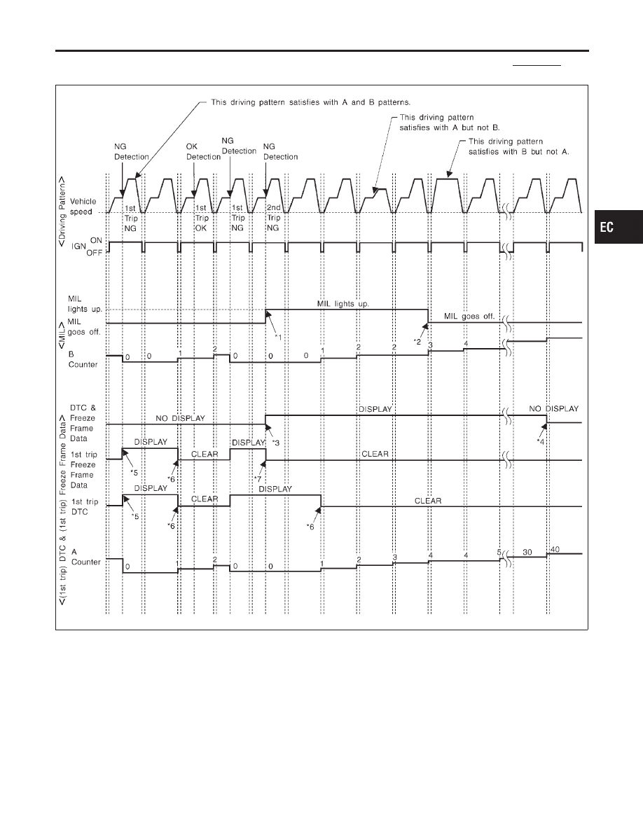
RELATIONSHIP BETWEEN MIL, DTC, 1ST TRIP DTC AND DRIVING PATTERNS EXCEPT
FOR “MISFIRE <EXHAUST QUALITY DETERIORATION>”, “FUEL INJECTION SYSTEM”

NBEC0033S05

SEF393S

*1: When the same malfunction is

detected in two consecutive trips,
MIL will light up.

*2: MIL will go off after vehicle is

driven 3 times (pattern B) without
any malfunctions.

*3: When the same malfunction is

detected in two consecutive trips,
the DTC and the freeze frame
data will be stored in ECM.

*4: The DTC and the freeze frame

data will not be displayed any
longer after vehicle is driven 40
times (pattern A) without the same
malfunction.
(The DTC and the freeze frame
data still remain in ECM.)

*5: When a malfunction is detected

for the first time, the 1st trip DTC

and the 1st trip freeze frame data
will be stored in ECM.

*6: 1st trip DTC will be cleared after

vehicle is driven once (pattern B)
without the same malfunction.

*7: When the same malfunction is

detected in the 2nd trip, the 1st
trip freeze frame data will be
cleared.

GI

MA

EM

LC

FE

AT

TF

PD

AX

SU

BR

ST

RS

BT

HA

SC

EL

IDX

ON BOARD DIAGNOSTIC SYSTEM DESCRIPTION

OBD System Operation Chart (Cont’d)

EC-79

EXPLANATION FOR DRIVING PATTERNS EXCEPT FOR “MISFIRE <EXHAUST QUALITY
DETERIORATION>”, “FUEL INJECTION SYSTEM”

NBEC0033S06

<Driving Pattern A>

NBEC0033S0601

AEC574

I

The A counter will be cleared when the malfunction is detected regardless of (1) - (4).

I

The A counter will be counted up when (1) - (4) are satisfied without the same malfunction.

I

The DTC will not be displayed after the A counter reaches 40.

<Driving Pattern B>

NBEC0033S0602

Driving pattern B means the vehicle operation as follows:
All components and systems should be monitored at least once by the OBD system.

I

The B counter will be cleared when the malfunction is detected once regardless of the driving pattern.

I

The B counter will be counted up when driving pattern B is satisfied without any malfunctions.

I

The MIL will go off when the B counter reaches 3 (*2 in “OBD SYSTEM OPERATION CHART”).

ON BOARD DIAGNOSTIC SYSTEM DESCRIPTION

OBD System Operation Chart (Cont’d)

EC-80

SEF941Y

CONSULT-II

=NBEC0034

CONSULT-II INSPECTION PROCEDURE

NBEC0034S01

1.

Turn ignition switch OFF.

2.

Connect CONSULT-II to data link connector, which is located
under LH dash panel near the fuse box cover.

PBR455D

3.

Turn ignition switch ON.

4.

Touch “START”.

SEF948Y

5.

Touch “ENGINE”.

SEF949Y

6.

Perform each diagnostic test mode according to each service
procedure.

For further information, see the CONSULT-II Operation
Manual.

GI

MA

EM

LC

FE

AT

TF

PD

AX

SU

BR

ST

RS

BT

HA

SC

EL

IDX

ON BOARD DIAGNOSTIC SYSTEM DESCRIPTION

CONSULT-II

EC-81

ENGINE CONTROL COMPONENT PARTS/CONTROL
SYSTEMS APPLICATION

NBEC0034S02

Item

DIAGNOSTIC TEST MODE

WORK

SUP-

PORT

SELF-DIAGNOSTIC

RESULTS

DATA

MONI-

TOR

DATA

MONI-

TOR

(SPEC)

ACTIVE

TEST

DTC & SRT

CONFIRMATION

DTC*1

FREEZE

FRAME
DATA*2

SRT

STATUS

DTC

WORK

SUP-

PORT

ENGINE

CONTROL

COMPONENT

P

ARTS

INPUT

Crankshaft position sensor
(POS)

X

X

X

X

Crankshaft position sensor (REF)

X

X

X

Mass air flow sensor

X

X

X

Engine coolant temperature sen-
sor

X

X

X

X

X

Heated oxygen sensor 1 (front)

X

X

X

X

X

Heated oxygen sensor 2 (rear)

X

X

X

X

X

Vehicle speed sensor

X

X

X

X

Throttle position sensor

X

X

X

Fuel tank temperature sensor

X

X

X

X

EVAP control system pressure
sensor

X

X

X

Absolute pressure sensor

X

X

X

Intake air temperature sensor

X

X

X

Knock sensor

X

Ignition switch (start signal)

X

X

Closed throttle position switch

X

X

X

Closed throttle position switch
(throttle position sensor signal)

X

X

Air conditioner switch

X

X

Park/neutral position (PNP)
switch

X

X

X

Power steering oil pressure
switch

X

X

Battery voltage

X

X

Ambient air temperature switch

X

X

Load signal

X

X

Swirl control valve control
vacuum check switch

X

X

X

Fuel level sensor

X

X

X

Intake valve timing control posi-
tion sensor

X

X

X

ON BOARD DIAGNOSTIC SYSTEM DESCRIPTION

CONSULT-II (Cont’d)

EC-82


Content   ..  151  152  153  154   ..