Infiniti QX4 (R50). Manual - part 140
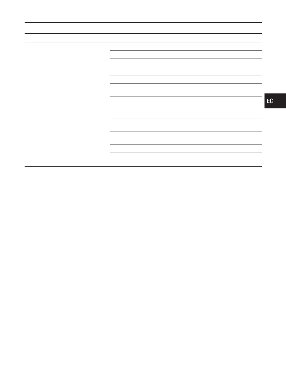
System Chart
NBEC0013
Input (Sensor)
ECM Function
Output (Actuator)
I
Camshaft position sensor (PHASE)
I
Crankshaft position sensor (REF)
I
Mass air flow sensor
I
Engine coolant temperature sensor
I
Heated oxygen sensor 1 (front)
I
Ignition switch
I
Throttle position sensor
I
Closed throttle position switch*3
I
Park/neutral position (PNP) switch
I
Air conditioner switch
I
Knock sensor
I
Intake air temperature sensor
I
Absolute pressure sensor
I
EVAP control system pressure sensor*1
I
Battery voltage
I
Power steering oil pressure switch
I
Vehicle speed sensor
I
Fuel tank temperature sensor*1
I
Crankshaft position sensor (POS)
I
Heated oxygen sensor 2 (rear)*2
I
TCM (Transmission control module)
I
Refrigerant pressure sensor
I
Electrical load
I
Fuel level sensor*1
Fuel injection & mixture ratio control
Injectors
Electronic ignition system
Power transistor
Idle air control system
IACV-AAC valve
Fuel pump control
Fuel pump relay
On board diagnostic system
MIL (On the instrument panel)
Swirl control valve control
Swirl control valve control solenoid
valve
Power valve control
VIAS control solenoid valve
Heated oxygen sensor 1 heater (front) con-
trol
Heated oxygen sensor 1 heater
(front)
Heated oxygen sensor 2 heater (rear) control
Heated oxygen sensor 2 heater
(rear)
EVAP canister purge flow control
EVAP canister purge volume con-
trol solenoid valve
Air conditioning cut control
Air conditioner relay
ON BOARD DIAGNOSIS for EVAP system
I
EVAP canister vent control valve
I
Vacuum cut valve bypass valve
*1: These sensors are not used to control the engine system. They are used only for the on board diagnosis.
*2: This sensor is not used to control the engine system under normal conditions.
*3: This switch will operate in place of the throttle position sensor to control EVAP parts if the sensor malfunctions.
GI
MA
EM
LC
FE
AT
TF
PD
AX
SU
BR
ST
RS
BT
HA
SC
EL
IDX
ENGINE AND EMISSION CONTROL OVERALL SYSTEM
System Chart
EC-27