Infiniti QX4 (R50). Manual - part 44
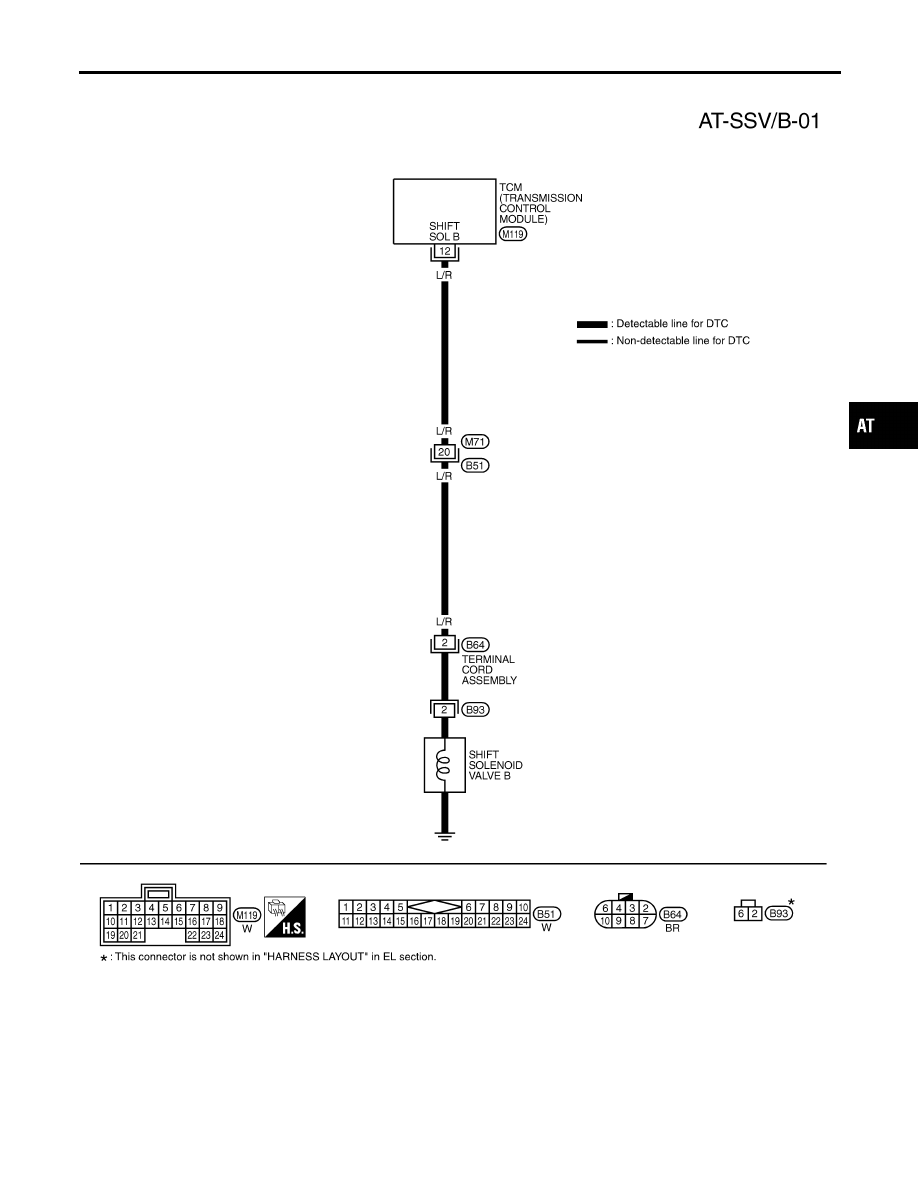
Wiring Diagram — AT — SSV/B
NBAT0198
MAT739A
GI
MA
EM
LC
EC
FE
TF
PD
AX
SU
BR
ST
RS
BT
HA
SC
EL
IDX
DTC P0755 SHIFT SOLENOID VALVE B
Wiring Diagram — AT — SSV/B
AT-173
|
|
|
Wiring Diagram — AT — SSV/B NBAT0198 MAT739A GI MA EM LC EC FE TF PD AX SU BR ST RS BT HA SC EL IDX DTC P0755 SHIFT SOLENOID VALVE B Wiring Diagram — AT — SSV/B AT-173 |