Infiniti QX4 (R50). Manual - part 10
SAT964I
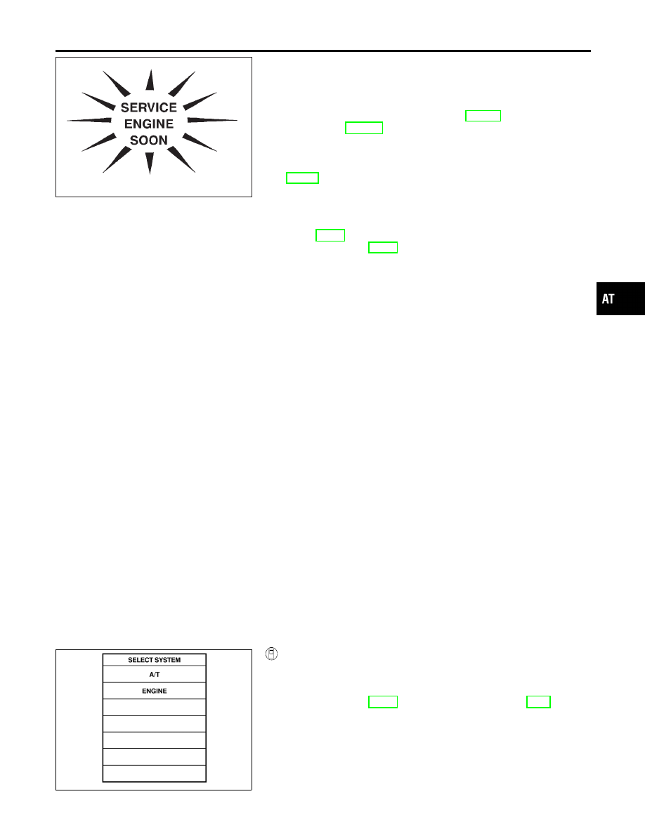
Malfunction Indicator Lamp (MIL)
=NBAT0183
The MIL is located on the instrument panel.
1.
The MIL will light up when the ignition switch is turned ON
without the engine running. This is a bulb check.
I
If the MIL does not light up, refer to EL-114, “Schematic”.
(Or refer to EC-648, “Wiring Diagram”.)
2.
When the engine is started, the MIL should go off.
If the MIL remains on, the on board diagnostic system has
detected an engine system malfunction. For detail, refer to
EC-59, “Introduction”.
CONSULT-II
NBAT0184
After performing “SELF-DIAGNOSTIC PROCEDURE (WITH CON-
SULT-II)” (AT-37), place check marks for results on the “DIAGNOS-
TIC WORKSHEET”, AT-55. Reference pages are provided follow-
ing the items.
NOTICE:
1)
The CONSULT-II electrically displays shift timing and lock-up
timing (that is, operation timing of each solenoid).
Check for time difference between actual shift timing and the
CONSULT-II display. If the difference is noticeable, mechani-
cal parts (except solenoids, sensors, etc.) may be malfunction-
ing. Check mechanical parts using applicable diagnostic pro-
cedures.
2)
Shift schedule (which implies gear position) displayed on
CONSULT-II and that indicated in Service Manual may differ
slightly. This occurs because of the following reasons:
I
Actual shift schedule has more or less tolerance or allowance,
I
Shift schedule indicated in Service Manual refers to the point
where shifts start, and
I
Gear position displayed on CONSULT-II indicates the point
where shifts are completed.
3)
Shift solenoid valve “A” or “B” is displayed on CONSULT-II at
the start of shifting. Gear position is displayed upon completion
of shifting (which is computed by TCM).
4)
Additional CONSULT-II information can be found in the Opera-
tion Manual supplied with the CONSULT-II unit.
SAT014K
SELF-DIAGNOSTIC PROCEDURE (WITH CONSULT-II)
NBAT0184S01
1.
Turn on CONSULT-II and touch “ENGINE” for OBD-II detected
items or touch “A/T” for TCM self-diagnosis.
If A/T is not displayed, check TCM power supply and ground
circuit. Refer to AT-92. If result is NG, refer to EL-9, “Sche-
matic”.
GI
MA
EM
LC
EC
FE
TF
PD
AX
SU
BR
ST
RS
BT
HA
SC
EL
IDX
ON BOARD DIAGNOSTIC SYSTEM DESCRIPTION
Malfunction Indicator Lamp (MIL)
AT-37