Infiniti Q45. Manual - part 688
FRONT FOG LAMP
LT-89
C
D
E
F
G
H
I
J
L
M
A
B
LT
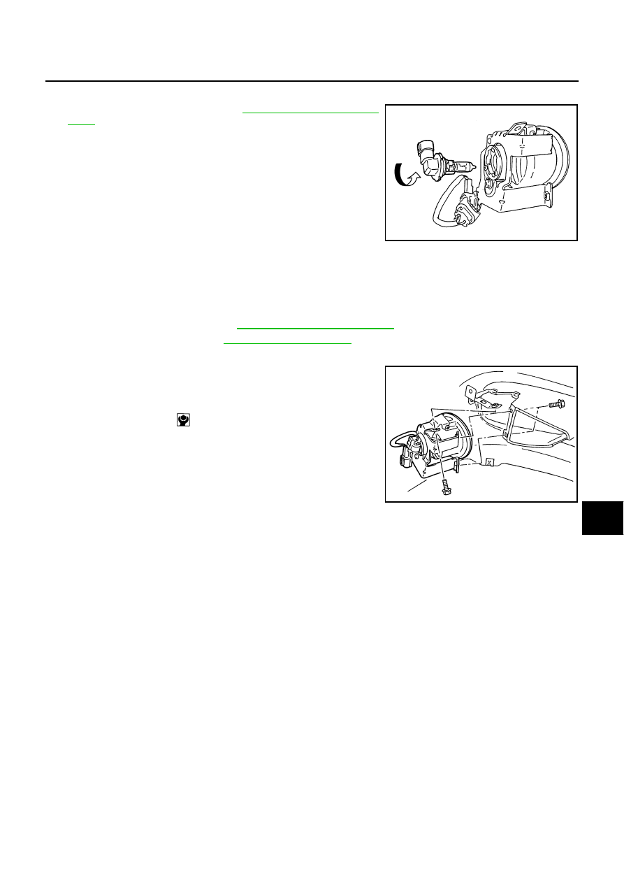
Bulb Replacement
NKS0018Y
1.
Remove fender protector. Refer to
.
2.
Disconnect front fog lamp connector.
3.
Turn bulb socket counterclockwise and unlock it.
CAUTION:
●
Never touch the glass of bulb directly by hand. Keep grease
and other oily matters away from it. Never touch bulb by
hand while it is lit or right after being turned off. Burning
may result.
●
Never leave bulb out of front fog lamp reflector for a long time because dust, moisture smoke, etc.
May affect the performance of front fog lamp. When replacing bulb, be sure to replace it with new
one.
Removal and Installation
NKS0018Z
REMOVAL
1.
Remove fender protector. Refer to
2.
Remove bumper grille. Refer to
3.
Disconnect front fog lamp connector.
4.
Remove front fog lamp mounting bolt from front fog lamp
bracket.
5.
Pull the lamp unit toward the rear of the vehicle and remove it.
INSTALLATION
Installation is the reverse order of removal.
Front fog lamp
: 12V - 51W (HB4 halogen)
PKIA9786E
Front fog lamp
mounting bolt
: 5.5 N·m (0.56 kg-m, 49 in-lb)
PKIA9788E