Index Infiniti Infiniti Q45 - service repair manual 2006 year
Search copyright infringement
Content .. 684 685 686 687 ..
Infiniti Q45. Manual - part 686
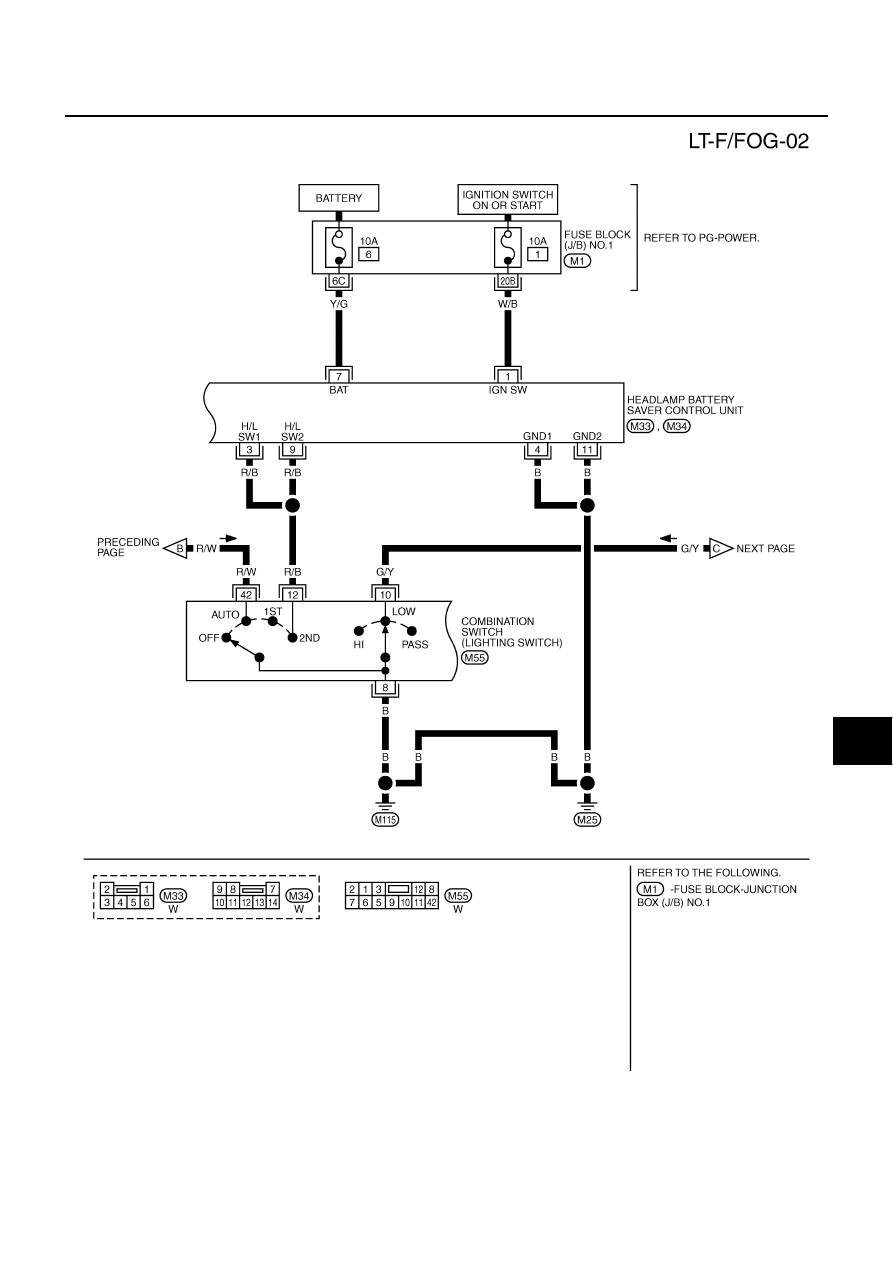
FRONT FOG LAMP
LT-81
C
D
E
F
G
H
I
J
L
M
A
B
LT
TKWM3721E