Infiniti Q45. Manual - part 316


  Index      Infiniti     Infiniti Q45 - service repair manual 2006 year


Search            copyright infringement  


Content   ..  314  315  316  317   ..


Infiniti Q45. Manual - part 316


VEHICLE INFORMATION AND INTEGRATED SWITCH SYSTEM /WITHOUT 

NAVIGATION SYSTEM

DI-131

C

D

E

F

G

H

I

J

L

M

A

B

DI

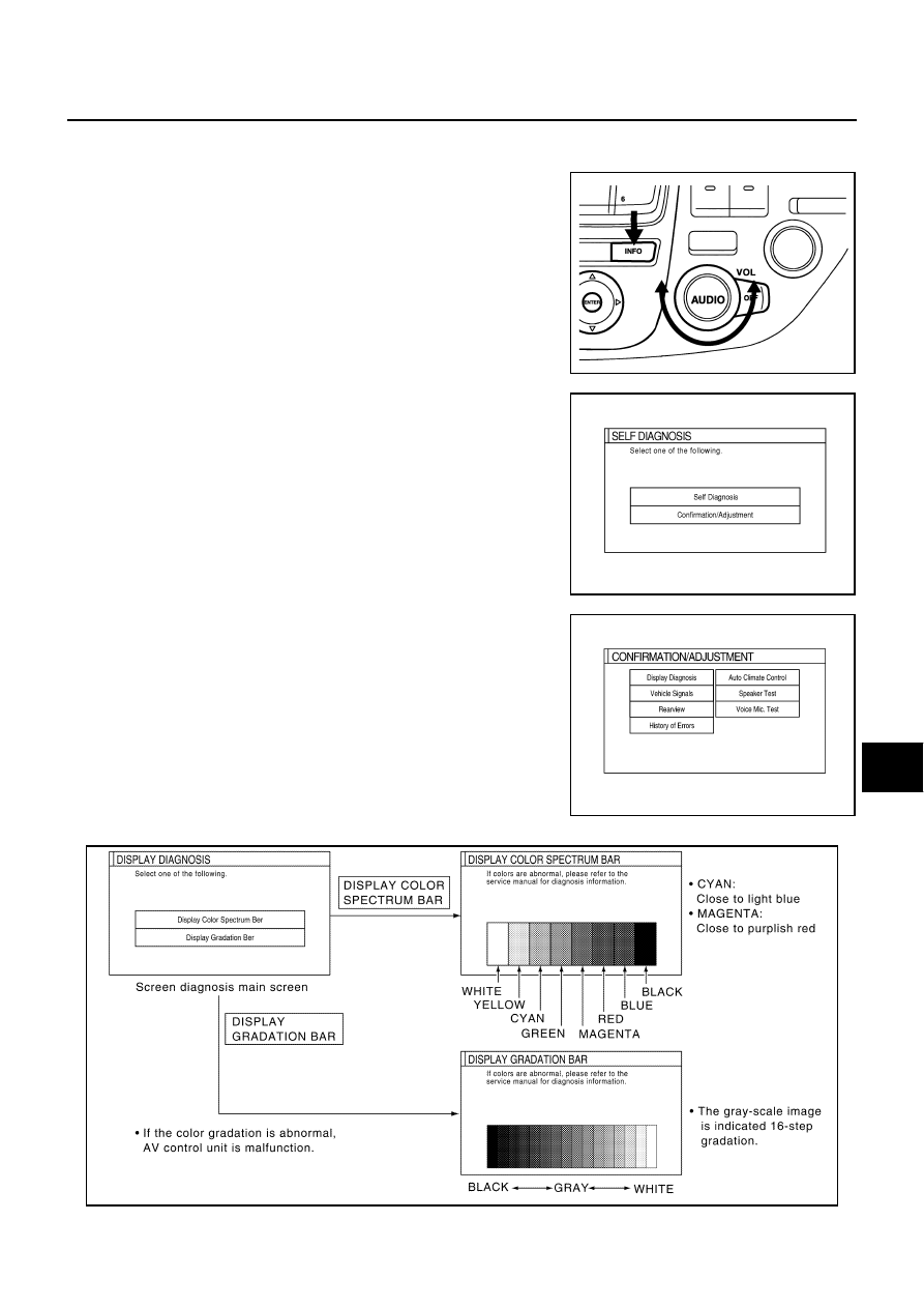
CONFIRMATION/ADJUSTMENT MODE
Operation Procedure

1.

Start the engine.

2.

Turn the audio system off.

3.

While pressing the “INFO” switch, turn the volume control dial
clockwise or counterclockwise for 30 clicks or more. (When the
self-diagnosis mode is started, a short beep will be heard.)

Shifting from current screen to previous screen is performed
by pressing “PREV” switch.

4.

The initial trouble diagnosis screen will be shown, and items
“Self Diagnosis” and “Confirmation/Adjustment” will become
selective.

5.

When “Confirmation/Adjustment” is selected on the initial trouble
diagnosis screen, the operation will enter the CONFIRMATION/
ADJUSTMENT mode. In this mode, check and adjustment of
each item will become possible.

6.

Select each switch on “Confirmation/Adjustment” screen to dis-
play the relevant diagnosis screen.

Display Diagnosis

PKIB0256E

SKIA0381E

SKIA5028E

SKIB0796E

DI-132

VEHICLE INFORMATION AND INTEGRATED SWITCH SYSTEM /WITHOUT 

NAVIGATION SYSTEM

CAUTION:

When DISPLAY COLOR SPECTRUM BAR screen is completed after “PREV” switch is pressed, the
screen color changes once. This is normal.

When RGB signal error occurred in the RGB system, tone of the color bar will change as follows.

When the color of the screen looks unusual, refer to 

DI-142, "Color of RGB Image Is Not Proper"

 .

Vehicle Signals

A comparison check can be made of each actual vehicle signal
and the signals recognized by the system.

Rear View Camera

Refer to 

DI-185, "Side Distance Guideline Correction"

  for the details.

Auto Climate Control

Refer to 

ATC-53, "Self-diagnosis Function"

  in ATC section for the details.

Speaker Test

Refer to 

AV-40, "Confirmation/Adjustment Mode"

  for the details.

CONSULT-II Function (MULTI AV)

NKS001CP

CONSULT-II can display each diagnostic item using the diagnostic test modes shown following.

R (red) signal error

: Screen looks bluish

G (green) signal error

: Screen looks yellowish

B (blue) signal error

: Screen looks reddish

PKIA9684E

Diagnosis item

Display

Condition

Remarks

Vehicle Speed

ON

Vehicle speed > 0 km/h (0 MPH)

Changes in indication may be delayed by 
approx. 1.5 seconds. This is normal.

OFF

Vehicle speed = 0 km/h (0 MPH)

Ignition switch in ACC position

Light

ON

Lighting switch ON

OFF

Lighting switch OFF

IGN

ON

Ignition switch ON

OFF

Ignition switch ACC or OFF

Reverse

ON

A/T selector lever “R” position

OFF

A/T selector lever in other “R” position

Ignition switch in ACC position

System part

Check item, diagnosis mode

Description

MULTI AV

VERSION

Displays unit version.

SELF-DIAG RESULTS

Checks for the connections AV communication line.

Performs the unit diagnosis.

SIGNAL MONITOR

Displays unified AV control unit. Input date in real time.

VEHICLE INFORMATION AND INTEGRATED SWITCH SYSTEM /WITHOUT 

NAVIGATION SYSTEM

DI-133

C

D

E

F

G

H

I

J

L

M

A

B

DI

CONSULT-II OPERATION

Refer to 

GI-36, "CONSULT-II Start Procedure"

 .

VERSION

Displays version of each unit connected to the AV control unit.

SELF-DIAGNOSIS RESULTS

The self-diagnosis is started and self-diagnosis results are displayed by touching “START” after selecting
“SELF-DIAG RESULTS”.

Display Item of SELF-DIAG RESULTS

Self-diagnosis results may be displayed simultaneously according to the cause. If some error items are dis-
played simultaneously, the detection of the cause can be performed by the combination of display items.
NOTE:
When “IVCS [ABNORMAL CONNECTION]” is indicated, this is not malfunction.

Version display

Remarks

“PANEL SW”

Multifunction switch

“HEAD UNIT”

AV control unit

“REAR VIEW CAMERA”

“FRONT SEAT DISPLAY”

Display

“AUDIO HEAD UNIT”

“AIR COMP RECEIVER”

Low Tire Pressure Warning Control Unit

“BOSE AMP”

“IVCS”

NOTE:
Although these items are shown on the CONSULT-II screen, 
impracticable. Because, these items are not applied.

“VOICE UNIT”

PKIA9680E

Error item

Possible cause

Action to take

HEAD UNIT
[ABNORMAL]

AV control unit malfunction is detected

Replace AV control unit

VOICE UNIT
[ABNORMAL]

Voice activated control module malfunction 
is detected

Replace voice activated control module

PANEL SW
[ABNORMAL CONNECTION]

AUDIO HEAD UNIT
[ABNORMAL CONNECTION]

AIR COMP RECEIVER
[ABNORMAL CONNECTION]

VOICE UNIT
[ABNORMAL CONNECTION]

BOSE AMP
[ABNORMAL CONNECTION]

FRONT SEAT DISPLAY
[ABNORMAL CONNECTION]

Malfunction is detected on communication 
signal

Check all communication circuits composing AV sys-
tem. Repair malfunctioning parts.

DI-134

VEHICLE INFORMATION AND INTEGRATED SWITCH SYSTEM /WITHOUT 

NAVIGATION SYSTEM

PANEL SW
[ABNORMAL CONNECTION]

AUDIO HEAD UNIT
[ABNORMAL CONNECTION]

AIR COMP RECEIVER
[ABNORMAL CONNECTION]

BOSE AMP
[ABNORMAL CONNECTION]

FRONT SEAT DISPLAY
[ABNORMAL CONNECTION]

Malfunction is detected on communication 
signal between AV control unit and display

1. Check communication circuit between AV control 

unit and display.

2. If the results from the above checkup show no mal-

function, replace either AV control unit or display, 
and then start self-diagnosis.

3. If self-diagnosis results still show any malfunction, 

replace the other unit.

PANEL SW
[ABNORMAL CONNECTION]

AUDIO HEAD UNIT
[ABNORMAL CONNECTION]

AIR COMP RECEIVER
[ABNORMAL CONNECTION]

BOSE AMP
[ABNORMAL CONNECTION]

Malfunction is detected on communication 
signal between display and multifunction 
switch

1. Check communication circuit between display and 

multifunction switch.

2. If the results from the above checkup show no mal-

function, replace either display or display, and then 
start self-diagnosis.

3. If self-diagnosis results still show any malfunction, 

replace the other unit.

PANEL SW
[ABNORMAL CONNECTION]

Multifunction switch power supply and 
ground circuit malfunction is detected

1. Check multifunction switch power supply and 

ground circuit.

2. If the results from the above checkup show no mal-

function, replace multifunction switch.

AUDIO HEAD UNIT
[ABNORMAL CONNECTION]

BOSE AMP
[ABNORMAL CONNECTION]

Malfunction is detected on communication 
signal between multifunction switch and 
audio unit

1. Check communication circuit between multifunction 

switch and audio unit.

2. If the results from the above checkup show no mal-

function, replace either multifunction switch or audio 
unit, and then start self-diagnosis.

3. If self-diagnosis results still show any malfunction, 

replace the other unit.

AIR COMP RECEIVER
[ABNORMAL CONNECTION]

Low tire pressure warning control unit 
power supply and ground circuit mal-
function is detected

Malfunction is detected on communica-
tion signal between multifunction switch 
and low tire pressure warning control 
unit

1. Check low tire pressure warning control unit power 

supply and ground circuit.

2. Check communication circuit between multifunction 

switch and low tire pressure warning control unit.

3. If the results from the above checkup show no mal-

function, replace either multifunction switch or low 
tire pressure warning control unit, and then start 
self-diagnosis.

4. If self-diagnosis results still show any malfunction, 

replace the other unit.

BOSE AMP
[ABNORMAL CONNECTION]

BOSE speaker amp. power supply and 
ground circuit malfunction is detected

Malfunction is detected on communica-
tion signal between audio unit and BOSE 
speaker amp.

1. Check BOSE speaker amp. power supply and 

ground circuit.

2. Check communication circuit between audio unit 

and BOSE speaker amp.

3. If the results from the above checkup show no mal-

function, replace either audio unit or BOSE speaker 
amp., and then start self-diagnosis.

4. If self-diagnosis results still show any malfunction, 

replace the other unit.

AUDIO HEAD UNIT
[ABNORMAL CONNECTION]

Audio unit power supply and ground circuit 
malfunction is detected

1. Check audio unit power supply circuit.

2. If the results from the above checkup show no mal-

function, replace audio unit.

Error item

Possible cause

Action to take


Content   ..  314  315  316  317   ..