Infiniti Q45. Manual - part 275
VDC/TCS/ABS CONTROL UNIT
BRC-65
[VDC/TCS/ABS]
C
D
E
G
H
I
J
K
L
M
A
B
BRC
VDC/TCS/ABS CONTROL UNIT
PFP:47660
Removal and Installation
NFS000DN
REMOVAL
1.
Remove instrument lower cover. Refer to
IP-15, "(O) Instrument Lower Cover"
2.
Remove instrument finisher. Refer to
3.
Remove grove box assembly. Refer to
.
4.
Remove grove box cover. Refer to
.
5.
Remove instrument panel bracket.
6.
Remove ECM. Refer to
EC-105, "ECM Terminals and Reference
.
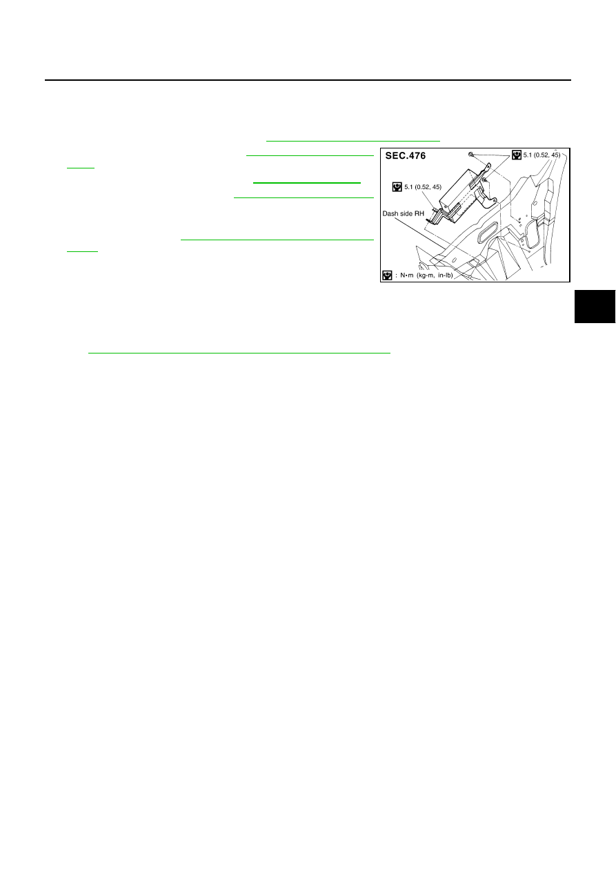
7.
Remove VDC/TCS/ABS control unit.
INSTALLATION
Installation in the reverse order of removal.
NOTE:
If the case that VDC/TCS/ABS control unit are replaced, make sure to adjust position of steering angle sensor.
Refer to
BRC-6, "Adjustment of Steering Angle Sensor Neutral Position"
SFIA2616E