Infiniti Q45 (FY33). Manual - part 545
Wiring Diagram
TST002M
GI
MA
EM
LC
EC
FE
AT
PD
FA
RA
BR
RS
BT
HA
EL
IDX
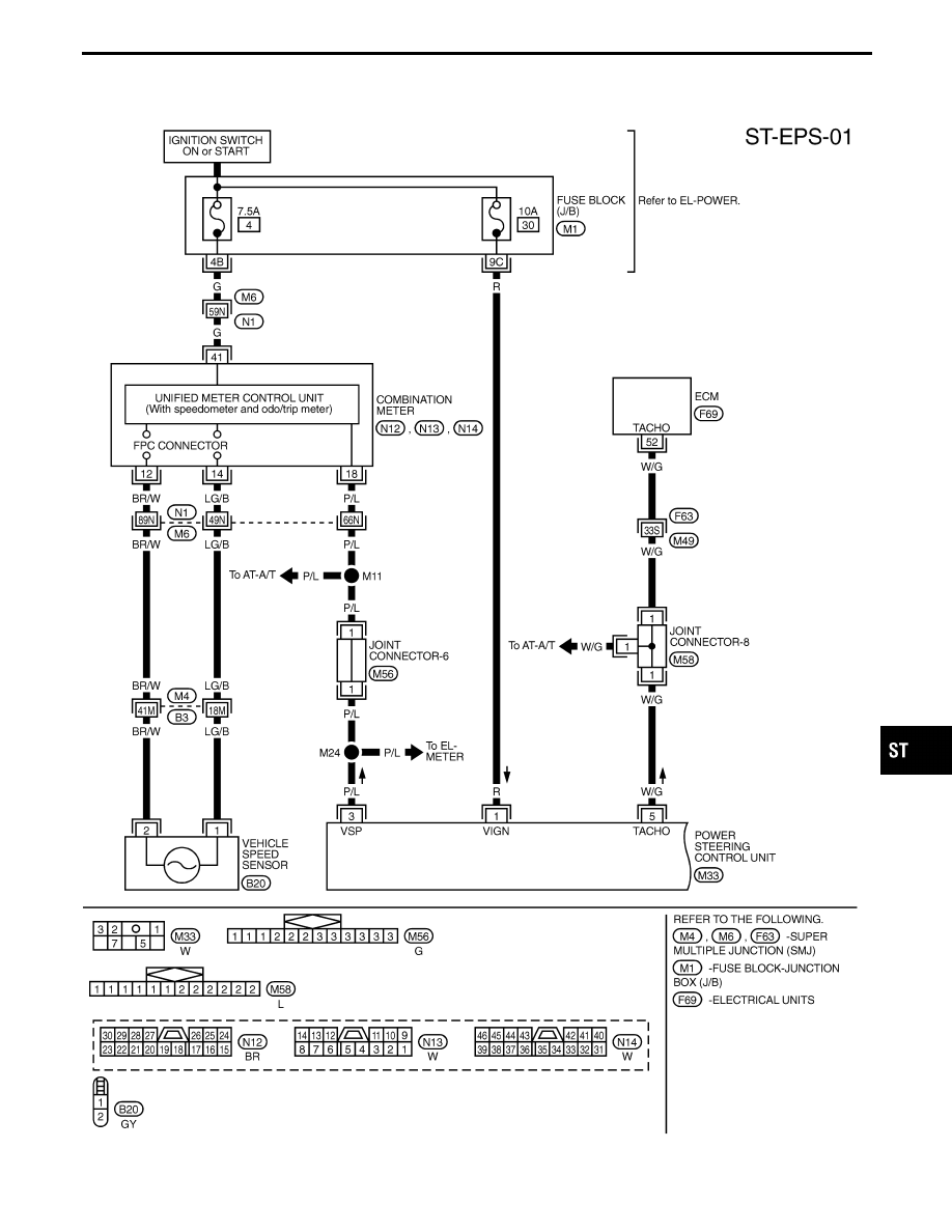
TWIN ORIFICE POWER STEERING SYSTEM
ST-31
|
|
|
Wiring Diagram TST002M GI MA EM LC EC FE AT PD FA RA BR RS BT HA EL IDX TWIN ORIFICE POWER STEERING SYSTEM ST-31 |