Infiniti Q45 (FY33). Manual - part 537
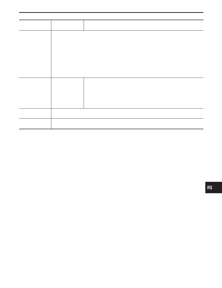
Part
Side air bag is acti-
vated
SRS is NOT activated
Seat belt pre-ten-
sioner assembly
1. Check if the seat belt can be extended smoothly.
If the seat belt cannot be extended smoothly.
- Check for deformities of the center pillar inner.
- If the center pillar inner has no damage, REPLACE the seat belt pre-tensioner assembly.
2. Remove the seat belt pre-tensioner assembly on the collision side. Check harness cover and connectors
for damage, terminals for deformities, and harness for binding.
3. Check for visible signs of damage (dents, cracks, deformation) of the seat belt pre-tensioner assembly.
4. If no damage is found, reinstall the seat belt pre-tensioner assembly with new bolts coated with bonding
agent.
5. If damaged—REPLACE the seat belt pre-tensioner assembly with new bolts coated with bonding agent.
The seat belt pre-tensioner assembly must be deployed before disposing of it.
Seat with built-in
type side air bag
REPLACE all parts
of seat back (includ-
ing seat back frame)
1. Visually check the seat on the collision side.
2. Remove the seat on the collision side and check the following for damage and
deformities.
I
Harness, connectors and terminals
I
Frame and recliner, and also adjuster and slides
3. If no damage is found, reinstall the seat.
4. If damaged—REPLACE the damaged seat parts with new bolts.
Center pillar inner
1. Check the center pillar inner on the collision side for damage (dents, cracks, deformation).
2. If damaged—REPAIR the center pillar inner.
Trim
1. Check for visible signs of damage (dents, cracks, deformation) of the interior trim on the collision side.
2. If damaged—REPLACE the damaged trim parts.
GI
MA
EM
LC
EC
FE
AT
PD
FA
RA
BR
ST
BT
HA
EL
IDX
COLLISION DIAGNOSIS
RS-63