Infiniti Q45 (FY33). Manual - part 449
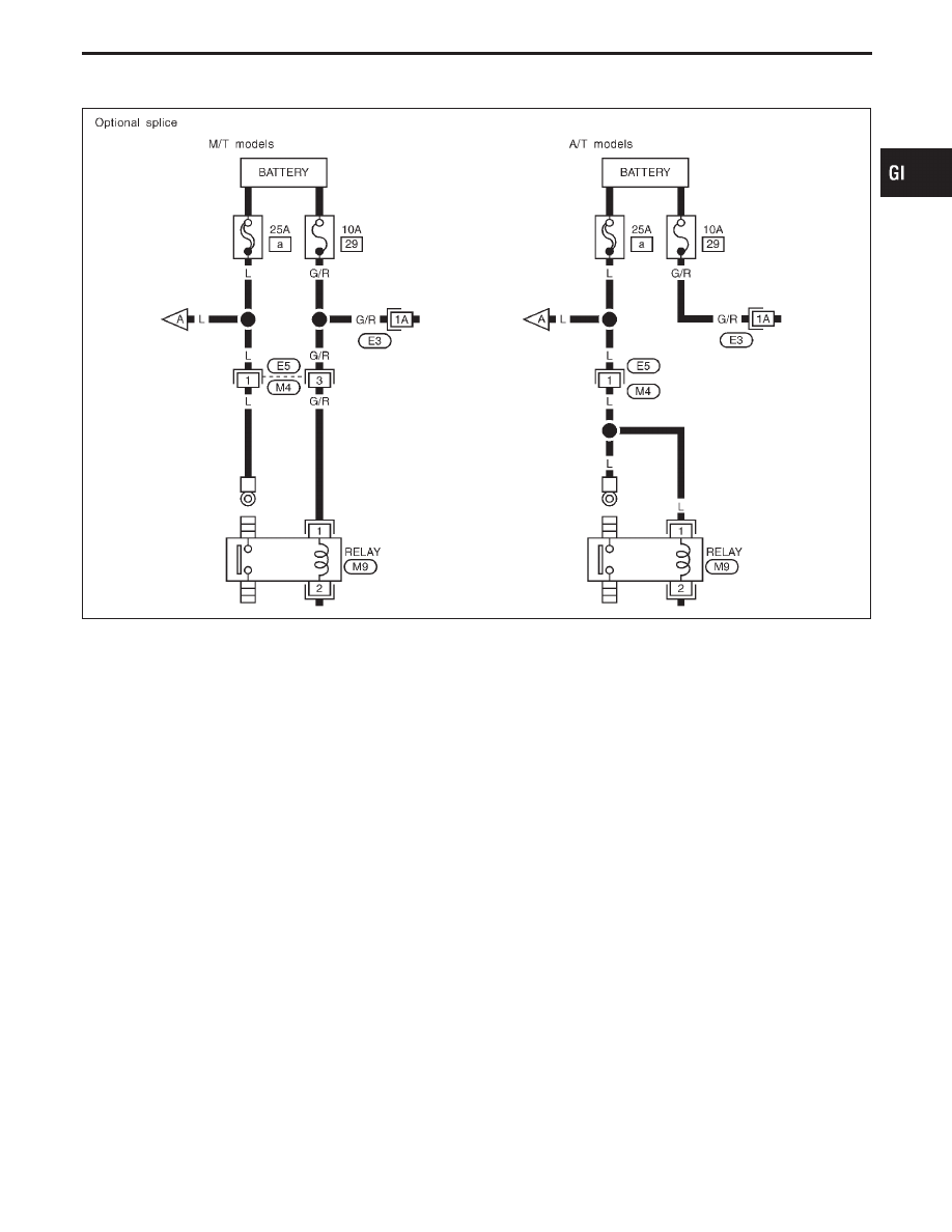
OPTIONAL SPLICE
SGI942
MA
EM
LC
EC
FE
AT
PD
FA
RA
BR
ST
RS
BT
HA
EL
IDX
HOW TO READ WIRING DIAGRAMS
Sample/Wiring Diagram — EXAMPL — (Cont’d)
GI-11
|
|
|
OPTIONAL SPLICE SGI942 MA EM LC EC FE AT PD FA RA BR ST RS BT HA EL IDX HOW TO READ WIRING DIAGRAMS Sample/Wiring Diagram — EXAMPL — (Cont’d) GI-11 |