Infiniti Q45 (FY33). Manual - part 376


  Index      Infiniti     Infiniti Q45 (FY33) - service repair manual 2001 year


Search            copyright infringement  


Content   ..  374  375  376  377   ..


Infiniti Q45 (FY33). Manual - part 376


SEL954W

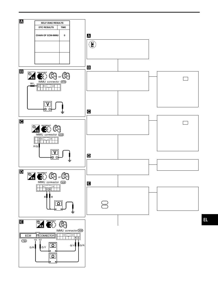
DIAGNOSTIC PROCEDURE 3

Self-diagnostic results:
“CHAIN OF ECM-IMMU” displayed on CONSULT-II screen

SEL867UA

SEL868UA

SEL869UA

SEL260V

Confirm SELF-DIAGNOSTIC
RESULTS “CHAIN OF ECM-
IMMU” displayed on CONSULT-II
screen.

OK

Check voltage between terminal

q

4

of

IMMU and ground with CONSULT-II or
tester.
Voltage: Battery voltage

OK

E

NG

Check the following:

I

7.5A fuse (No. 57 ,
located in the fuse, fus-
ible link and relay box)

I

Harness for open or
short between fuse and
IMMU connector

Ref. part No. C1

Check voltage between terminal

q

3

of

IMMU and ground with CONSULT-II or
tester.
Voltage: Battery voltage

OK

E

NG

Check the following:

I

7.5A fuse [No. 32 ,
located in the fuse block
(J/B)]

I

Harness for open or
short between fuse and
IMMU connector

Ref. part No. C2

Check harness continuity between IMMU
terminal

q

8

or

q

9

and ground.

Continuity should exist.

OK

E

NG

Repair harness.
Ref. part No. C3

Check harness continuity between the fol-
lowing ECM terminals and IMMU termi-
nals.

ECM

102

and IMMU

q

6

ECM

103

and IMMU

q

5

Continuity should exist.

OK

E

NG

Communication line is
open circuit.
Repair harness or connec-
tors.
Ref. part No. C4

q

A

GI

MA

EM

LC

EC

FE

AT

PD

FA

RA

BR

ST

RS

BT

HA

IDX

IVIS (Infiniti Vehicle Immobilizer System — NATS)

Trouble Diagnoses (Cont’d)

H

H

H

H

H

EL-495

SEL261V

SEL262V

SEL903VB

SEL955W

SEL714W

q

A

CHECK COMMUNICATION LINE CIR-
CUIT.
1. Disconnect ECM connector and IMMU

connector.

2. Check voltage between the following

terminals and ground.
ECM

102

, ECM

103

, IMMU

q

5

and

IMMU

q

6

Voltage: 0V

OK

E

NG

Communication line is
short-circuited with battery
voltage line or ignition
switch ON line.
Repair harness or connec-
tors.
Ref. part No. C4

Check continuity between the following
terminals and ground.
ECM

102

, ECM

103

, IMMU

q

5

and

IMMU

q

6

Continuity should not exist.

OK

E

NG

Communication line is
short-circuited with ground
line.
Repair harness or connec-
tors.
Ref. part No. C4

CHECK POWER SUPPLY FOR IVIS
(NATS) ANTENNA AMP.
1. Connect IMMU connector and IVIS

(NATS) antenna amp. connector.

2. Check voltage between IVIS (NATS)

antenna amp. terminal

q

1

and ground

(Power supply from IVIS (NATS) IMMU
terminal

q

2

) with analogue tester.

Before turning ignition switch “ON”

Voltage: 0V

Just after turning ignition switch “ON”

Pointer of tester should move.

OK

E

NG

IVIS (NATS) antenna amp.
+5V line is short-circuited
with battery voltage line or
ground line.
Repair harness or connec-
tors.
Ref. part No. E3

SELF-FUNCTION CHECK
1. Connect ECM connector and

disconnect IMMU connector.

2. Turn ignition switch “ON”.
3. Touch “SELF-FUNCTION

CHECK” on CONSULT-II
“SELECT DIAG MODE” screen.

(See next page.)

Touch “START”. ECM will then
check its communication interface
by itself.

OK

E

NG

ECM is malfunctioning.
Replace ECM.
Ref. part No. B

Perform initialisa-
tion with CON-
SULT-II.
For the operation of
initialization, refer
to “CONSULT-II
operation manual
IVIS/NVIS”.

q

B

IVIS (Infiniti Vehicle Immobilizer System — NATS)

Trouble Diagnoses (Cont’d)

H

H

H

H

H

H

H

EL-496

q

B

IMMU is malfunctioning.
Replace IMMU.
Ref. part No. A

Perform initialization with CON-
SULT-II.
For the operation of initialization,
refer to “CONSULT-II operation
manual IVIS/NVIS”.

SEL956W

DIAGNOSTIC PROCEDURE 4

Self-diagnostic results:
“DIFFERENCE OF KEY” displayed on CONSULT-II screen

SEL566W

Confirm SELF-DIAGNOSTIC
RESULTS “DIFFERENCE OF
KEY” displayed on CONSULT-II
screen.

OK

Perform initialization with CON-
SULT-II.
Re-register all NATS ignition key
IDs.
For the operation of initialization,
refer to “CONSULT-II operation
manual IVIS/NVIS”.

Initialization
completed

Initialization
with CON-
SULT-II
incomplete or
failed

E

IMMU is malfunc-
tioning.
Replace IMMU.
Ref. part No. A

Start engine.

END
(Ignition key ID was unregistered.)
Ref. part No. D

Perform initializa-
tion with CON-
SULT-II.
For the operation
of initialization,
refer to “CON-
SULT-II operation
manual IVIS/NVIS”.

GI

MA

EM

LC

EC

FE

AT

PD

FA

RA

BR

ST

RS

BT

HA

IDX

IVIS (Infiniti Vehicle Immobilizer System — NATS)

Trouble Diagnoses (Cont’d)

H

H

H

H

H

H

EL-497

SEL957W

DIAGNOSTIC PROCEDURE 5

Self-diagnostic results:
“CHAIN OF IMMU-KEY” displayed on CONSULT-II screen

SEL903VB

SEL904VB

SEL905VB

Confirm SELF-DIAGNOSTIC
RESULTS “CHAIN OF IMMU-KEY”
displayed on CONSULT-II screen.

OK

Perform initializa-
tion with CON-
SULT-II.
For the operation of
initialization, refer
to “CONSULT-II
operation manual
IVIS/NVIS”.

G

CHECK IVIS (NATS) IGNITION KEY ID
CHIP.
Start engine with another registered IVIS
(NATS) ignition key.

Start NG

Start
OK

E

Ignition key ID chip was
malfunctioning.
Replace the ignition key.
Ref. part No. E5

CHECK IVIS (NATS) ANTENNA AMP.
INSTALLATION.
Refer to “How to Replace IVIS (NATS)
Antenna Amp.” in EL-503.

OK

E

NG

Reinstall IVIS (NATS)
antenna amp. correctly.

CHECK POWER SUPPLY FOR IVIS
(NATS) ANTENNA AMP.
1. Connect IMMU connector and IVIS

(NATS) antenna amp. connector.

2. Check voltage between IVIS (NATS)

antenna amp. terminal

q

1

and ground

(Power supply from IVIS (NATS) IMMU
terminal

q

2

) with analogue tester.

Before turning ignition switch “ON”

Voltage: 0V

Just after turning ignition switch “ON”

Pointer of tester should move.

OK

E

NG

Check harness for open or
short between for open or
short between IMMU and
IVIS (NATS) antenna amp.
If harness is OK, replace
IMMU, perform initialisation
with CONSULT-II.
For the initialisation
procedure, refer to “CON-
SULT-II operation manual
IVIS/NVIS”.

G

CHECK SIGNAL LINE 1 BETWEEN
IMMU AND IVIS (NATS) ANTENNA AMP.
Check voltage between IVIS (NATS)
antenna amp. terminal

q

2

and ground with

analogue tester. Before turning ignition
switch “ON”
Voltage: 0V
Just after turning ignition switch “ON”
Pointer of tester should move.

OK

E

NG

CHECK SIGNAL LINE 2 BETWEEN
IMMU AND IVIS (NATS) ANTENNA AMP.
Check voltage between IVIS (NATS)
antenna amp. terminal

q

3

and ground with

analogue tester. Before turning ignition
switch “ON”
Voltage: 4.5 - 5V
Just after turning ignition switch “ON”
Pointer of tester should move.

OK

NG

q

A

IVIS (Infiniti Vehicle Immobilizer System — NATS)

Trouble Diagnoses (Cont’d)

H

H

H

H

H

H

EL-498


Content   ..  374  375  376  377   ..