Infiniti Q45 (FY33). Manual - part 277
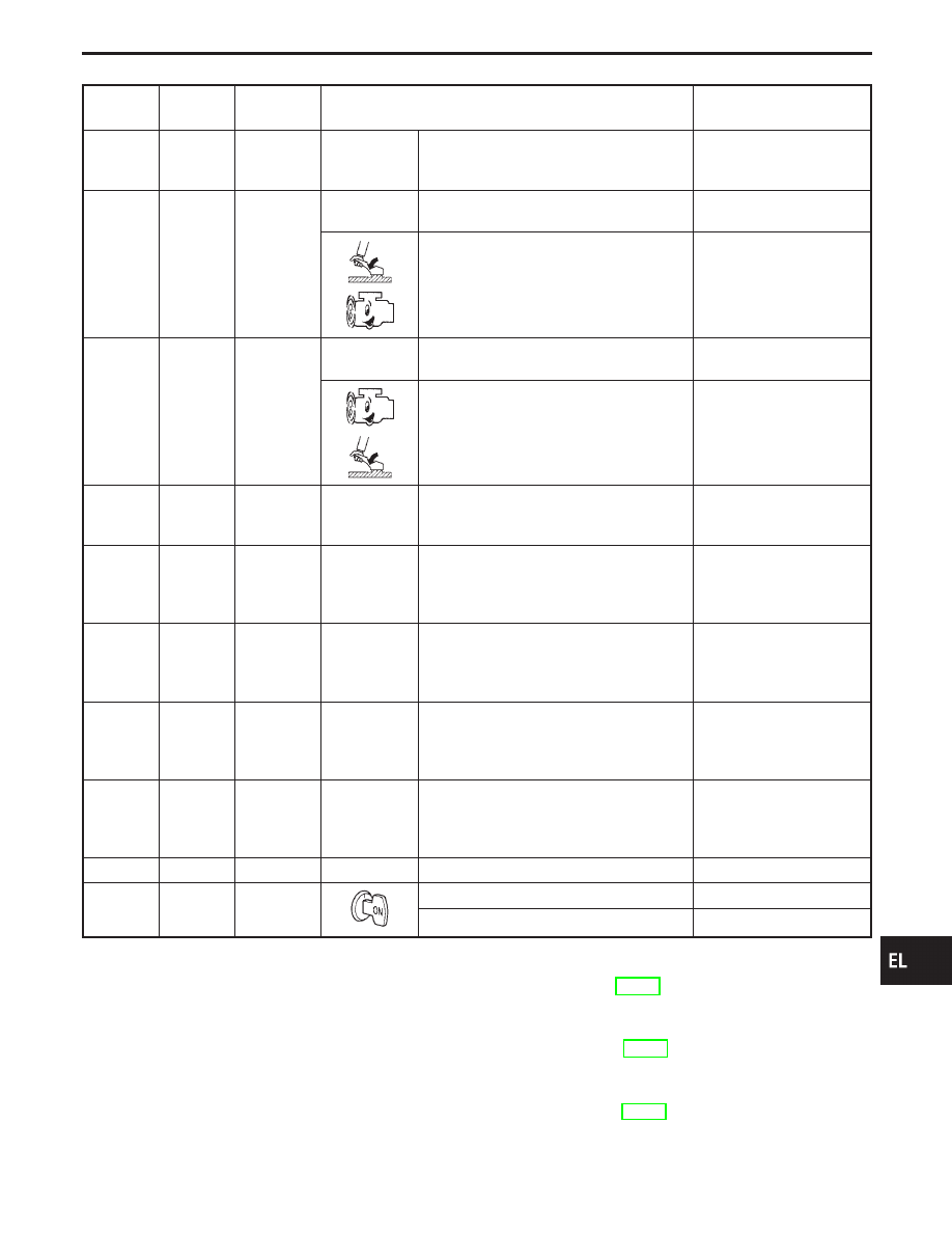
Terminal
No.
Wire color
Item
Condition
Judgement
standard
8
R/W
RH low
beam
(Ground)
When turning lighting switch “2ND” and
LOW (“B”) position
Less than 1V
9
B/W
RH high
beam
(Ground)
When turning lighting switch to “2ND” and
HIGH (“A”) or PASS (“C”) positions
Less than 1V
When releasing parking brake with engine
running and turning lighting switch to “OFF”
(daytime light operation)
CAUTION:
Block wheels and ensure
selector lever is in N or P position.
Approx. half battery voltage
10
R
LH high
beam
(Ground)
When turning lighting switch to “2ND” and
HIGH (“A”) or PASS (“C”) positions
Less than 1V
When releasing parking brake with engine
running and turning lighting switch to “OFF”
(daytime light operation)
CAUTION:
Block wheels and ensure
selector lever is in N or P position.
Less than 1V
11
G/W
LH low
beam
(Ground)
When turning lighting switch “2ND” and
LOW (“B”) position
Less than 1V
12
Y/B
Lighting
switch
(LH low
beam)
When turning lighting switch “2ND” and
LOW (“B”) position
Less than 1V
13
W
Lighting
switch
(LH high
beam)
When turning lighting switch “2ND” and
HIGH (“A”) or PASS (“C”) position
Less than 1V
14
B/W
Lighting
switch
(RH high
beam)
When turning lighting switch “2ND” and
HIGH (“A”) or PASS (“C”) position
Less than 1V
15
G/Y
Lighting
switch
(RH low
beam)
When turning lighting switch “2ND” and
LOW (“B”) position
Less than 1V
16
B
Ground
—
—
17
OR
Parking
brake switch
When parking brake is released
Battery voltage
When parking brake is set
Less than 1.5V
Bulb Replacement/Conventional Type
For bulb replacement, refer to EL-76.
Bulb Specifications/Conventional Type
For bulb specifications, refer to EL-76.
Aiming Adjustment/Conventional Type
For aiming adjustment, refer to EL-76.
GI
MA
EM
LC
EC
FE
AT
PD
FA
RA
BR
ST
RS
BT
HA
IDX
HEADLAMP (FOR CANADA) — CONVENTIONAL TYPE —
Trouble Diagnoses (Cont’d)
EL-99