Infiniti Q45 (FY33). Manual - part 140
Work Flow
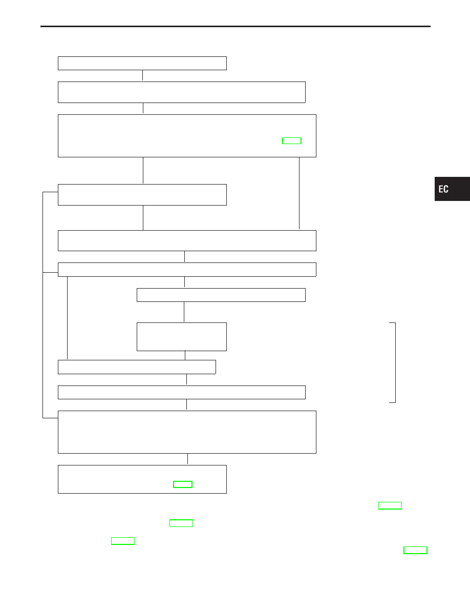
CHECK IN
CHECK INCIDENT CONDITIONS.
Listen to customer complaints. (Get symptoms.)
................................................. STEP I
CHECK DTC and FREEZE FRAME DATA.
Check and PRINT OUT (write down), (1st trip) Diagnostic Trouble Code (DTC) and
Freeze Frame Data (Pre-check). Then clear. Paste it in repair order sheet.
If DTC is not available even if MIL lights up, check ECM fail-safe. (Refer to EC-98.)
Also check related service bulletins for information.
*3
........................................... STEP II
Symptoms collected
No symptoms, except MIL
lights up, or (1st trip)
DTC exists at STEP II.
Verify the symptom by driving in the condition the cus-
tomer described.
H
*1
............................................................................................. STEP III
Normal Code
(at STEP II)
Malfunction Code
(at STEP II)
INCIDENT INFORMATION
Verify the (1st trip) DTC by performing the “DTC CONFIRMATION PROCEDURE”.
*1
........................................... STEP IV
E
Choose the appropriate action.
Malfunction Code (at STEP II or IV)
Normal Code (at both STEP II and IV)
...........................................
*2
STEP V
BASIC INSPECTION
SYMPTOM BASIS (at STEP I or III)
...............................................................
E
Perform inspections accord-
ing to Symptom Matrix
Chart.
H
TROUBLE DIAGNOSIS FOR DTC PXXXX.
*4
STEP VI
REPAIR/REPLACE
NG FINAL CHECK
Confirm that the incident is completely fixed by performing BASIC INSPECTION and
DTC CONFIRMATION PROCEDURE (or OVERALL FUNCTION CHECK).
Then, erase the unnecessary (already fixed) DTCs in ECM and TCM (Transmission
Control Module).
OK
........................................... STEP VII
CHECK OUT
If completion of SRT is needed, drive the vehicle
under the specific pattern. Refer to EC-56.
*1: If the incident cannot be duplicated, see “TROUBLE DIAGNOSIS FOR INTERMITTENT INCIDENT”, EC-117.
*2: If the on board diagnostic system cannot be performed, check main power supply and ground circuit (See TROUBLE
DIAGNOSIS FOR POWER SUPPLY, EC-118).
*3: If time data of “SELF-DIAG RESULTS” is other than “0” or “1t” refer to “TROUBLE DIAGNOSIS FOR
INTERMITTENT”, EC-117.
*4: If the malfunction part cannot be found, refer to “TROUBLE DIAGNOSIS FOR INTERMITTENT INCIDENT”, EC-117.
GI
MA
EM
LC
FE
AT
PD
FA
RA
BR
ST
RS
BT
HA
EL
IDX
TROUBLE DIAGNOSIS — Work Flow
H
H
H
H
H
H
H
H
H
H
H
EC-89