Infiniti Q45 (FY33). Manual - part 74
SBR435B
2.
Remove valve stopper while piston is pushed into cylinder.
SBR939A
3.
Remove piston assemblies.
If it is difficult to remove secondary piston assembly, gradu-
ally apply compressed air through fluid outlet.
— For TOKICO make —
4.
Draw out reservoir tank.
SBR231E
— For NABCO make —
4.
Drive out spring pin from cylinder body.
5.
Draw out reservoir tank and seals.
Inspection
Check master cylinder inner wall for pin holes or scratches.
Replace if damaged.
SBR089C
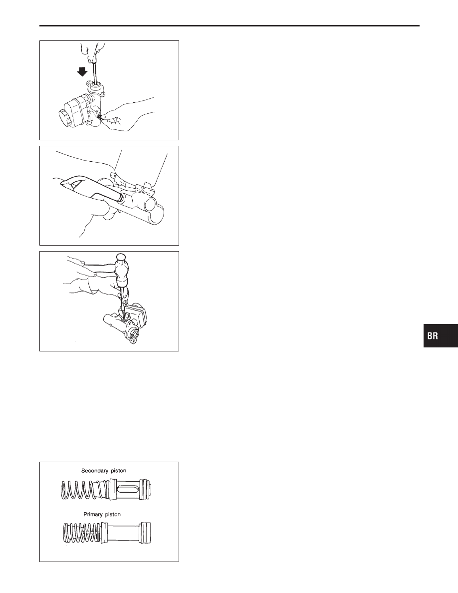
Assembly
1.
Insert secondary piston assembly. Then insert primary piston
assembly.
I
Pay attention to direction of piston cups in figure at left.
Also, insert pistons squarely to avoid scratches on cylin-
der bore.
I
Pay attention to alignment of secondary piston slit with
valve stopper mounting hole of cylinder body.
GI
MA
EM
LC
EC
FE
AT
PD
FA
RA
ST
RS
BT
HA
EL
IDX
MASTER CYLINDER
Disassembly (Cont’d)
BR-13