Infiniti Q45 (FY33). Manual - part 75


  Index      Infiniti     Infiniti Q45 (FY33) - service repair manual 2001 year


Search            copyright infringement  


Content   ..  73  74  75  76   ..


Infiniti Q45 (FY33). Manual - part 75


SBR577E

SBR454D

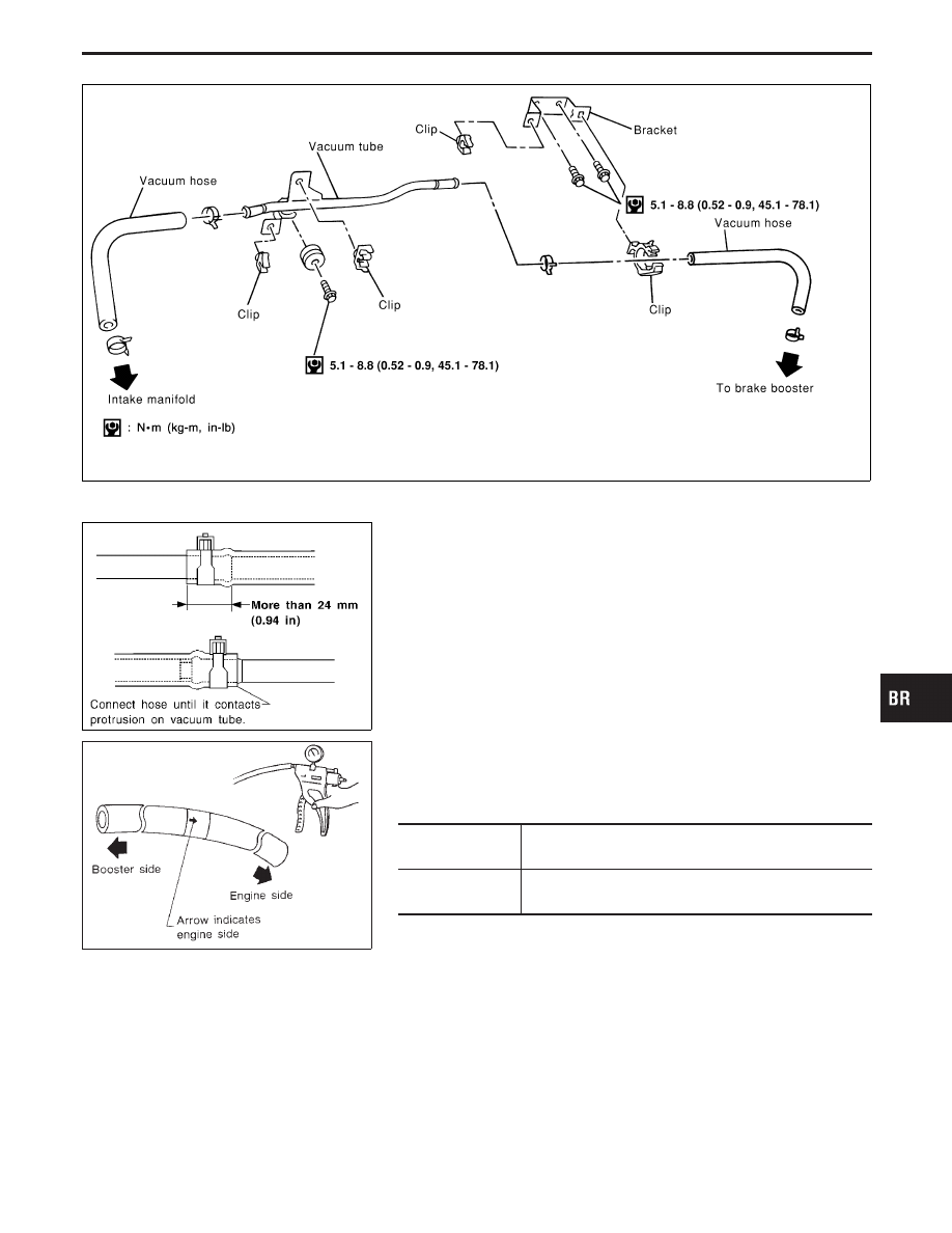
Removal and Installation

CAUTION:

When installing vacuum hoses, pay attention to the following
points.

I

Do not apply any oil or lubricants to vacuum hose and
check valve.

I

Insert vacuum tube into vacuum hose as shown.

I

Install check valve, paying attention to its direction.

SBR844B

Inspection

CHECK VALVE

Check vacuum with a vacuum pump.

Connect to booster
side

Vacuum should exist.

Connect to engine
side

Vacuum should not exist.

GI

MA

EM

LC

EC

FE

AT

PD

FA

RA

ST

RS

BT

HA

EL

IDX

VACUUM HOSE

BR-17

Pad Replacement

WARNING:

Clean brakes with a vacuum dust collector to minimize the
hazard of airborne particles or other materials.

CAUTION:

I

When cylinder body is open, do not depress brake pedal,
or piston will pop out.

I

Be careful not to damage piston boot or get oil on rotor.
Always replace shims when replacing pads.

I

If shims are rusted or show peeling of the rubber coat,
replace them with new shims.

I

It is not necessary to remove connecting bolt except for
disassembly or replacement of caliper assembly. In this
case, suspend cylinder body with wire so as not to stretch
brake hose.

I

Carefully monitor brake fluid level because brake fluid will
return to reservoir when pushing back piston.

I

Burnish the brake contact surfaces after refinishing or
replacing drums or rotors, after replacing pads or linings,
or if a soft pedal occurs at very low mileage. Refer to
“Brake Burnishing Procedure”, “ON-VEHICLE SERVICE”,
BR-6.

SBR433D

1.

Remove master cylinder reservoir cap.

2.

Remove lower pin bolt.

SBR040C

3.

Open cylinder body upward. Then remove pad retainers, and
inner and outer shims.

Standard pad thickness:

11.0 mm (0.433 in)

Pad wear limit:

2.0 mm (0.079 in)

I

Carefully monitor brake fluid level because brake fluid will
return to reservoir when pushing back piston.

FRONT DISC BRAKE

BR-18

Components

SBR615DA

q

1

Main pin

q

2

Pin boot

q

3

Torque member fixing bolt

q

4

Torque member

q

5

Shim cover

q

6

Inner shim

q

7

Inner pad

q

8

Pad retainer

q

9

Outer pad

q

10

Outer shim

q

11

Connecting bolt

q

12

Copper washer

q

13

Main pin bolt

q

14

Bleed valve

q

15

Cylinder body

q

16

Piston seal

q

17

Piston

q

18

Piston boot

q

19

Pad spring

Removal

WARNING:

Clean brake pads with a vacuum dust collector to minimize the
hazard of airborne particles or other materials.

CAUTION:

Suspend caliper assembly with wire so as not to stretch brake
hose.

SBR434D

Remove torque member fixing bolts and connecting bolt.
It is not necessary to remove connecting bolt except for dis-
assembly or replacement of caliper assembly. In this case,
suspend caliper assembly with wire so as not to stretch brake
hose.

GI

MA

EM

LC

EC

FE

AT

PD

FA

RA

ST

RS

BT

HA

EL

IDX

FRONT DISC BRAKE

BR-19

SBR085A

Disassembly

WARNING:

Do not place your fingers in front of piston.

CAUTION:

Do not scratch or score cylinder wall.
1.

Push out piston with dust seal with compressed air.

2.

Remove piston seal with a suitable tool.

Inspection — Caliper

CYLINDER BODY

I

Check inside surface of cylinder for score, rust, wear, damage
or presence of foreign objects. If any of the above conditions
are observed, replace cylinder body.

I

Minor damage from rust or foreign objects may be eliminated
by polishing surface with a fine emery paper. Replace cylinder
body if necessary.

CAUTION:

Use brake fluid to clean. Never use mineral oil.

PISTON

Check piston for score, rust, wear, damage or presence of foreign
objects. Replace if any of the above conditions are observed.

CAUTION:

Piston sliding surface is plated. Do not polish with emery
paper even if rust or foreign objects are stuck to sliding sur-
face.

MAIN PIN, PIN BOLT AND PIN BOOT

Check for wear, cracks, rust or other damage. Replace if any of the
above conditions are observed.

SBR019B

Inspection — Rotor

RUNOUT

1.

Secure rotor to wheel hub with at least two nuts (M12

×

1.25).

2.

Check runout using a dial indicator.

Make sure that wheel bearing axial end play is within the
specifications before measuring. Refer to FA section, 
“Front
Wheel Bearing”.

Maximum runout:

0.07 mm (0.0028 in)

3.

If the runout is out of specification, find minimum runout posi-
tion as follows:
a. Remove nuts and rotor from wheel hub.
b. Shift the rotor one hole and secure rotor to wheel hub with

nuts.

c. Measure runout.
d. Repeat steps a. to c. so that minimum runout position can

be found.

4.

If the runout is still out of specification, turn rotor with on-car
brake lathe (“MAD, DL-8700”, “AMMCO 700 and 705” or
equivalent).

FRONT DISC BRAKE

BR-20


Content   ..  73  74  75  76   ..