Infiniti Q45 (FY33). Manual - part 68
SAT986A
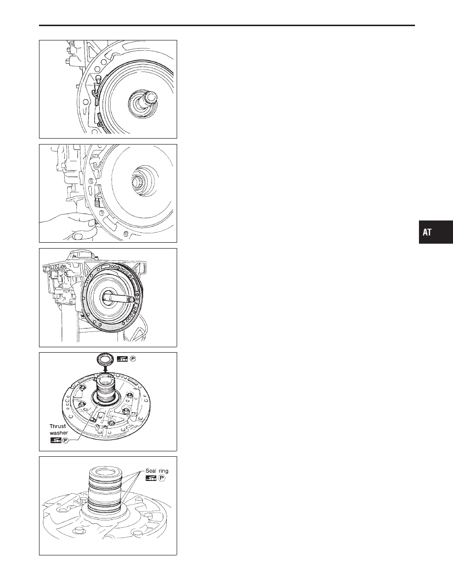
b.
Place brake band on periphery of reverse clutch drum, and
insert band strut into end of band servo piston stem.
SAT987A
c.
Install anchor end pin on transmission case. Then, tighten
anchor end pin just enough so that reverse clutch drum (clutch
pack) will not tilt forward.
SAT988A
2.
Install input shaft on transmission case.
I
Pay attention to its direction — O-ring groove side is front.
3.
Install gasket on transmission case.
SAT989A
4.
Install oil pump assembly.
a.
Install needle bearing on oil pump assembly.
I
Apply petroleum jelly to the needle bearing.
b.
Install selected thrust washer on oil pump assembly.
I
Apply petroleum jelly to thrust washer.
SAT990A
c.
Carefully install seal rings into grooves and press them into the
petroleum jelly so that they are a tight fit.
GI
MA
EM
LC
EC
FE
PD
FA
RA
BR
ST
RS
BT
HA
EL
IDX
ASSEMBLY
Assembly (2) (Cont’d)
AT-269