Infiniti Q45 (FY33). Manual - part 44


  Index      Infiniti     Infiniti Q45 (FY33) - service repair manual 2001 year


Search            copyright infringement  


Content   ..  42  43  44  45   ..


Infiniti Q45 (FY33). Manual - part 44


SAT582I

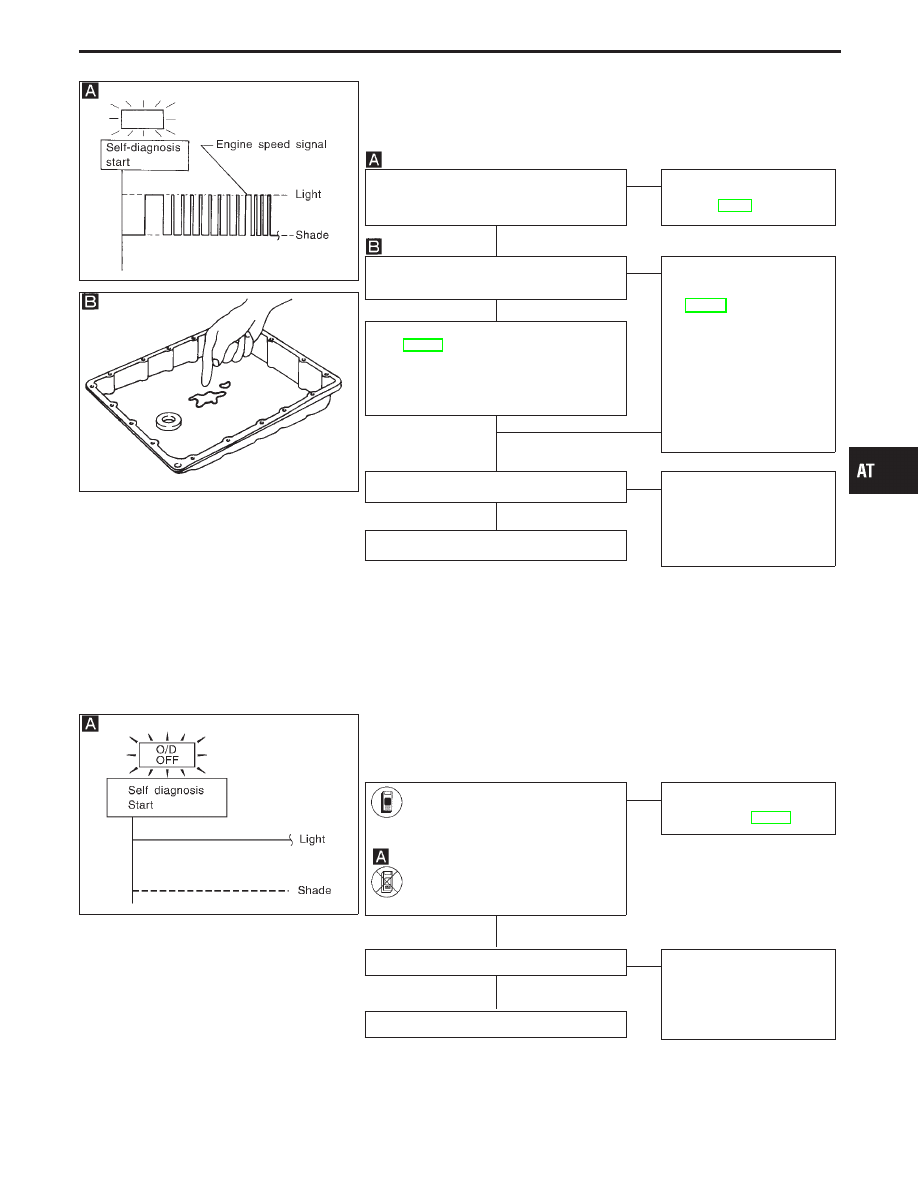
13. A/T Does Not Hold Lock-up Condition

SYMPTOM:

A/T does not hold lock-up condition for more than 30 seconds.

SAT171B

Does self-diagnosis show damage to
engine speed signal circuit after cruise
test?

No

E

Yes

Check engine speed signal
circuit. Refer to “DTC
P0725”, AT-92.

1. Remove oil pan.
2. Check A/T fluid condition.

OK

E

NG

1. Remove control valve

assembly. Refer to
AT-195.

2. Check the following

items:

I

Torque converter clutch
control valve

I

Pilot valve

I

Pilot filter

3. Disassemble A/T.
4. Check torque converter

and oil pump assembly.

1. Remove control valve assembly. Refer

to AT-195.

2. Check the following items:

I

Torque converter clutch control valve

I

Pilot valve

I

Pilot filter

OK

OK

F

Check again.

OK

E

NG

1. Perform TCM input/

output signal inspection.

2. If NG, recheck TCM pin

terminals for damage or
loose connection with
harness connector.

INSPECTION END

SAT367J

14. Lock-up Is Not Released

SYMPTOM:

Lock-up is not released when accelerator pedal is released.

Does “TCM INPUT SIGNALS” in
“DATA MONITOR” show damage to
closed throttle position switch cir-
cuit?

-------------------------------------------------------------------------------------------------------------------------------------- OR --------------------------------------------------------------------------------------------------------------------------------------

Does self-diagnosis show damage
to closed throttle position switch
circuit?

No

E

Yes

Check closed throttle posi-
tion switch circuit. Refer to
“DTC P1705”, AT-137.

Check again.

OK

E

NG

1. Perform TCM input/

output signal inspection.

2. If NG, recheck TCM pin

terminals for damage or
loose connection with
harness connector.

INSPECTION END

GI

MA

EM

LC

EC

FE

PD

FA

RA

BR

ST

RS

BT

HA

EL

IDX

TROUBLE DIAGNOSES FOR SYMPTOMS

H

H

H

H

H

H

H

AT-173

SAT583I

15. Engine Speed Does Not Return To Idle
(Light Braking D

4

D

3

)

SYMPTOM:

I

Engine speed does not smoothly return to idle when A/T
shifts from D

4

to D

3

.

I

Vehicle does not decelerate by engine brake when turning
overdrive control switch OFF.

I

Vehicle does not decelerate by engine brake when shifting
A/T from “D” to “2” position.

SAT559I

SAT171B

Does self-diagnosis show damage to
overrun clutch solenoid valve circuit after
cruise test?

No

E

Yes

Check overrun clutch sole-
noid valve circuit. Refer to
“DTC P1760”, AT-143.

Check throttle position sensor. Refer to
EC section [“Throttle Position Sensor
(DTC: 0403)”, “TROUBLE DIAGNOSIS
FOR DTC P0120”].

OK

E

NG

Repair or replace throttle
position sensor.

1. Remove oil pan.
2. Check A/T fluid condition.

OK

E

NG

1. Remove control valve

assembly. Refer to
AT-195.

2. Check the following

items:

I

Overrun clutch control
valve

I

Overrun clutch reducing
valve

I

Overrun clutch solenoid
valve

3. Disassemble A/T.
4. Check the following

items:

I

Overrun clutch assembly

I

Oil pump assembly

1. Remove control valve assembly. Refer

to AT-195.

2. Check the following items:

I

Overrun clutch control valve

I

Overrun clutch reducing valve

I

Overrun clutch solenoid valve

OK

OK

F

Check again.

OK

E

NG

1. Perform TCM input/

output signal inspection.

2. If NG, recheck TCM pin

terminals for damage or
loose connection with
harness connector.

INSPECTION END

TROUBLE DIAGNOSES FOR SYMPTOMS

H

H

H

H

H

H

AT-174

SAT686I

16. Vehicle Does Not Start From D

1

SYMPTOM:

Vehicle does not start from D

1

on Cruise test — Part 2.

Does self-diagnosis show damage to
vehicle speed sensor

A/T (revolution

sensor), shift solenoid valve A, B or
vehicle speed sensor

MTR after cruise

test?

No

E

Yes

Check damaged circuit.
Refer to “DTC P0720,
P0750, P0755 or VHCL
SPEED SEN

MTR”, AT-89,

129, 133 or 151.

Check again.

OK

E

NG

1. Perform TCM input/

output signal inspection.

2. If NG, recheck TCM pin

terminals for damage or
loose connection with
harness connector.

Go to 8. Vehicle Cannot Be Started From
D

1

AT-168.

SAT146BA

17. A/T Does Not Shift: D

4

D

3

, When

Overdrive Control Switch “ON”

“OFF”

SYMPTOM:

A/T does not shift from D

4

to D

3

when changing overdrive

control switch to “OFF” position.

Does “TCM INPUT SIGNALS” in
“DATA MONITOR” show damage
to overdrive control switch circuit?

-------------------------------------------------------------------------------------------------------------------------------------- OR --------------------------------------------------------------------------------------------------------------------------------------

Does self-diagnosis show damage
to overdrive control switch circuit?

No

E

Yes

Check overdrive control
switch circuit. Refer to
AT-177.

Go to 10. A/T Does Not Shift: D

2

,

D

3

,

AT-170.

GI

MA

EM

LC

EC

FE

PD

FA

RA

BR

ST

RS

BT

HA

EL

IDX

TROUBLE DIAGNOSES FOR SYMPTOMS

H

H

H

H

AT-175

SAT367J

18. A/T Does Not Shift: D

3

2

2

, When Selector

Lever “D”

“2” Position

SYMPTOM:

A/T does not shift from D

3

to 2

2

when changing selector lever

from “D” to “2” position.

Does “TCM INPUT SIGNALS” in
“DATA MONITOR” show damage
to PNP switch circuit?

-------------------------------------------------------------------------------------------------------------------------------------- OR --------------------------------------------------------------------------------------------------------------------------------------

Does self-diagnosis show damage
to PNP switch circuit?

No

E

Yes

Check PNP switch circuit.
Refer to “FOR DTC
P0705”, AT-81.

Go to 9. A/T Does Not Shift: D

1

,

D

2

Or

Does Not Kickdown: D

4

,

D

2

AT-169.

SAT367J

19. A/T Does Not Shift: 2

2

1

1

, When Selector

Lever “2”

“1” Position

SYMPTOM:

A/T does not shift from 2

2

to 1

1

when changing selector lever

from “2” to “1” position.

SAT778B

Does “TCM INPUT SIGNALS” in
“DATA MONITOR” show damage
to PNP switch circuit?

-------------------------------------------------------------------------------------------------------------------------------------- OR --------------------------------------------------------------------------------------------------------------------------------------

Does self-diagnosis show damage
to PNP switch circuit?

No

E

Yes

Check PNP switch circuit.
Refer to “DTC P0705”,
AT-81.

Check again.

OK

E

NG

1. Perform TCM input/

output signal inspection.

2. If NG, recheck TCM pin

terminals for damage or
loose connection with
harness connector.

INSPECTION END

TROUBLE DIAGNOSES FOR SYMPTOMS

H

H

H

AT-176


Content   ..  42  43  44  45   ..