Infiniti Q45 (FY33). Manual - part 43
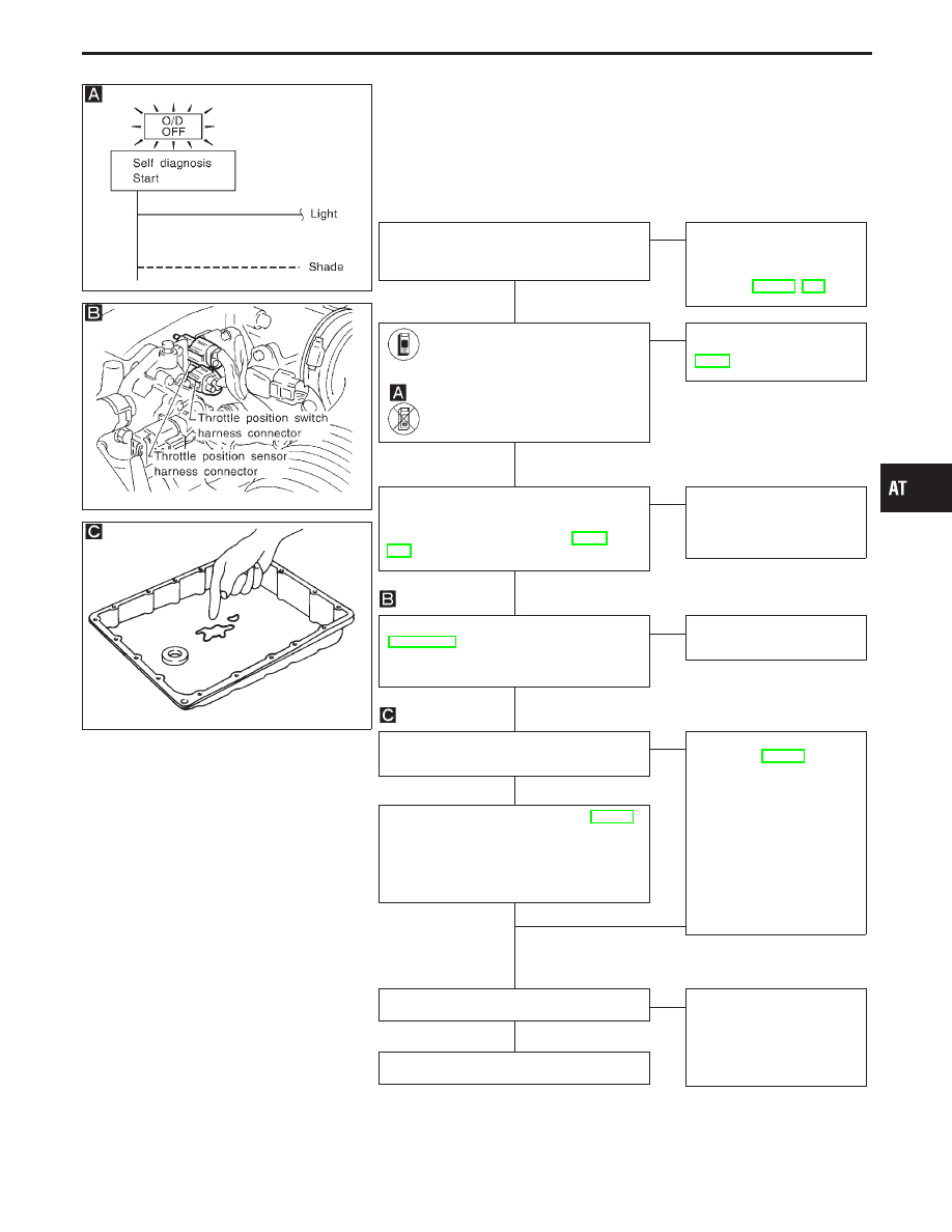
SAT367J
9. A/T Does Not Shift: D
1
→
D
2
Or Does Not
Kickdown: D
4
→
D
2
SYMPTOM:
A/T does not shift from D
1
to D
2
at the specified speed.
A/T does not shift from D
4
to D
2
when depressing accelerator
pedal fully at the specified speed.
SAT559I
SAT171B
Are 7. Vehicle Does Not Creep Forward In
“D”, “2” Or “1” Position and 8. Vehicle
Cannot Be Started From D
1
OK?
Yes
E
No
Go to 7. Vehicle Does Not
Creep Forward In “D”, “2”
Or “1” Position and 8.
Vehicle Cannot Be Started
From D
1
Does “TCM INPUT SIGNALS” in
“DATA MONITOR” show damage
to PNP switch circuit?
-------------------------------------------------------------------------------------------------------------------------------------- OR --------------------------------------------------------------------------------------------------------------------------------------
Does self-diagnosis show damage
to PNP switch circuit?
No
E
Yes
Check PNP switch circuit.
Refer to “DTC P0705”,
AT-81.
Check vehicle speed sensor
⋅
A/T (revolu-
tion sensor) and vehicle speed
sensor
⋅
MTR circuit. Refer to “DTC P0720
and VHCL SPEED SEN
⋅
MTR”, AT-89,
OK
E
NG
Repair or replace vehicle
speed sensor
⋅
A/T (revolu-
tion sensor) and vehicle
speed sensor
⋅
MTR circuits.
Check throttle position sensor. Refer to
EC section [“Throttle Position Sensor
(DTC: 0403)”, “TROUBLE DIAGNOSIS
FOR DTC P0120”].
OK
E
NG
Repair or replace throttle
position sensor.
1. Remove oil pan.
2. Check A/T fluid condition.
OK
E
NG
1. Remove control valve.
Refer to AT-195.
2. Check the following
items:
I
Shift valve A
I
Shift solenoid valve A
I
Pilot valve
I
Pilot filter
3. Disassemble A/T.
4. Check the following
items:
I
Servo piston assembly
I
Brake band
I
Oil pump assembly
1. Remove control valve. Refer to AT-195.
2. Check the following items:
I
Shift valve A
I
Shift solenoid valve A
I
Pilot valve
I
Pilot filter
OK
OK
F
Check again.
OK
E
NG
1. Perform TCM input/
output signal inspection.
2. If NG, recheck TCM pin
terminals for damage or
loose connection with
harness connector.
INSPECTION END
GI
MA
EM
LC
EC
FE
PD
FA
RA
BR
ST
RS
BT
HA
EL
IDX
TROUBLE DIAGNOSES FOR SYMPTOMS
H
H
H
H
H
H
H
H
AT-169