Infiniti Q45 (FY33). Manual - part 24
SAT014K
SEF949Y
DIAGNOSTIC TROUBLE CODE (DTC) CONFIRMA-
TION PROCEDURE
CAUTION:
Always drive vehicle at a safe speed.
NOTE:
If “DIAGNOSTIC TROUBLE CODE CONFIRMATION PROCE-
DURE” has been previously conducted, always turn ignition
switch “OFF” and wait at least 5 seconds before conducting
the next test.
After the repair, perform the following procedure to confirm the
malfunction is eliminated.
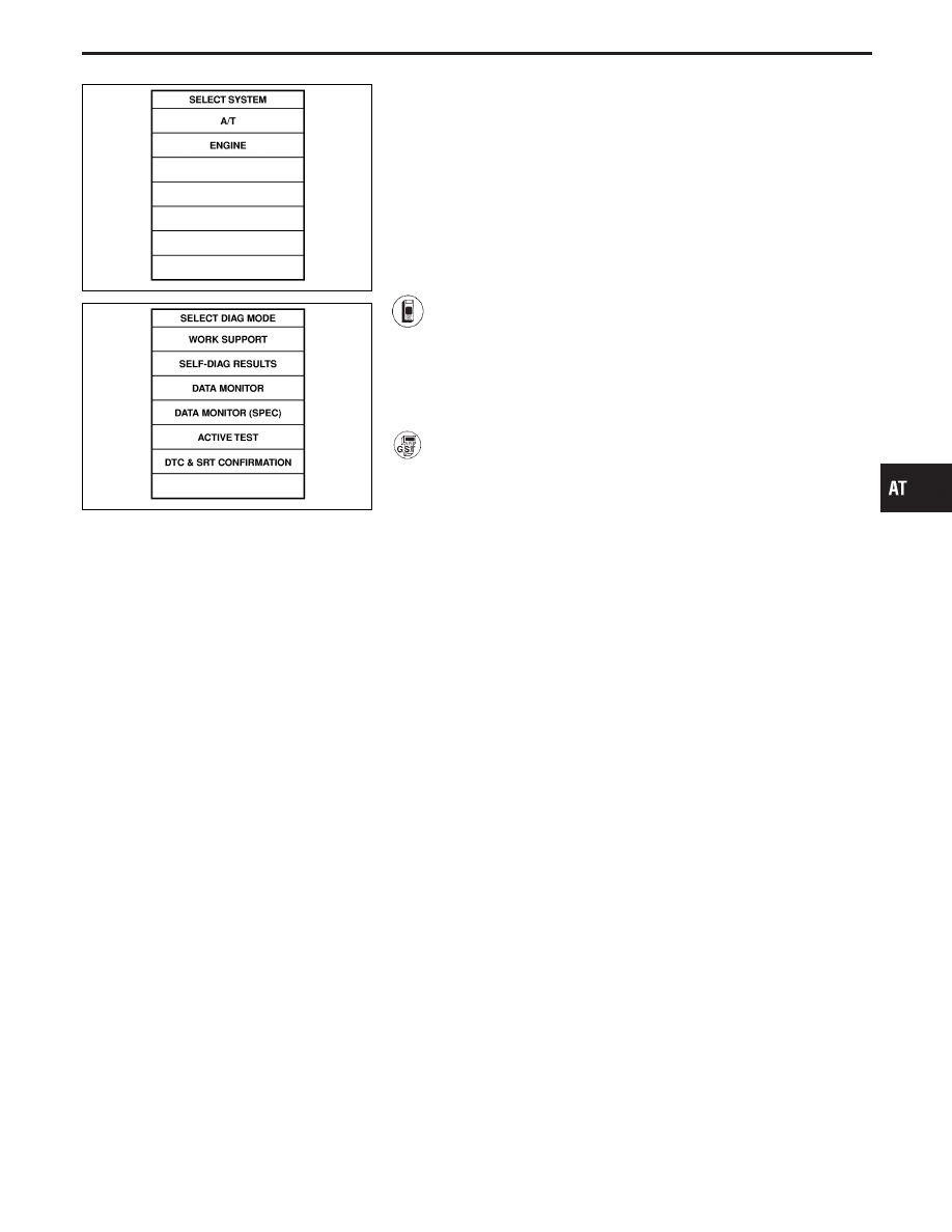
1)
Turn ignition switch “ON” and select “DATA MONITOR”
mode for “ENGINE” with CONSULT-II.
2)
Start engine and maintain the following conditions for at
least 10 consecutive seconds.
VHCL SPEED SE: 10 km/h (6 MPH) or more
THRTL POS SEN: More than 1.2V
Selector lever: D position (OD “ON”)
------------------------------------------------------------------------------------------------------------------------------------------------------------------------------------------------------------------------------------------------------ OR ------------------------------------------------------------------------------------------------------------------------------------------------------------------------------------------------------------------------------------------------------
Follow the procedure “With CONSULT-II”.
GI
MA
EM
LC
EC
FE
PD
FA
RA
BR
ST
RS
BT
HA
EL
IDX
TROUBLE DIAGNOSIS FOR DTC P0725
Engine Speed Signal (Cont’d)
AT-93