Infiniti Q45 (FY33). Manual - part 11


  Index      Infiniti     Infiniti Q45 (FY33) - service repair manual 2001 year


Search            copyright infringement  


Content   ..  9  10  11  12   ..


Infiniti Q45 (FY33). Manual - part 11


SAT286KA

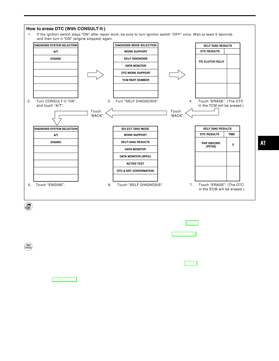
HOW TO ERASE DTC (With GST)

1. If the ignition switch stays “ON” after repair work, be sure to turn ignition switch “OFF” once. Wait at least

5 seconds and then turn it “ON” (engine stopped) again.

2. Perform “OBD-II SELF-DIAGNOSTIC PROCEDURE (No Tools)”. Refer to AT-49. (The engine warm-up step

can be skipped when performing the diagnosis only to erase the DTC.)

3. Select Mode 4 with Generic Scan Tool (GST). For details, refer to EC section [“Generic Scan Tool (GST)”,

“ON BOARD DIAGNOSTIC SYSTEM DESCRIPTION”].

HOW TO ERASE DTC (No Tools)

1. If the ignition switch stays “ON” after repair work, be sure to turn ignition switch “OFF” once. Wait at least

5 seconds and then turn it “ON” (engine stopped) again.

2. Perform “TCM SELF-DIAGNOSTIC PROCEDURE (No Tools)”. Refer to AT-49. (The engine warm-up step

can be skipped when performing the diagnosis only to erase the DTC.)

3. Change the diagnostic test mode from Mode II to Mode I by turning the mode selector on the ECM.

Refer to EC section [“HOW TO SWITCH DIAGNOSTIC TEST MODES”, “Malfunction Indicator Lamp
(MIL)”, “ON BOARD DIAGNOSTIC SYSTEM DESCRIPTION”].

GI

MA

EM

LC

EC

FE

PD

FA

RA

BR

ST

RS

BT

HA

EL

IDX

ON BOARD DIAGNOSTIC SYSTEM DESCRIPTION

OBD-II Diagnostic Trouble Code (DTC) (Cont’d)

AT-41

SAT964I

Malfunction Indicator Lamp (MIL)

1.

The malfunction indicator lamp will light up when the ignition
switch is turned ON without the engine running. This is for
checking the blown lamp.

I

If the malfunction indicator lamp does not light up, refer to EL
section 
(“WARNING LAMPS”).
(Or refer to EC section, “MIL & Data Link Connectors”.)

2.

When the engine is started, the malfunction indicator lamp
should go off.
If the lamp remains on, the on board diagnostic system has
detected an emission-related (OBD-II) malfunction. For detail,
refer to EC section (“ON BOARD DIAGNOSTIC SYSTEM
DESCRIPTION”).

CONSULT-II

NOTICE

1. The CONSULT-II electrically displays shift timing and lock-up timing (that is, operation timing of each

solenoid).
Check for time difference between actual shift timing and the CONSULT-II display. If the difference is
noticeable, mechanical parts (except solenoids, sensors, etc.) may be malfunctioning. Check mechanical
parts using applicable diagnostic procedures.

2. Shift schedule (which implies gear position) displayed on CONSULT-II and that indicated in Service Manual

may differ slightly. This occurs because of the following reasons:

I

Actual shift schedule has more or less tolerance or allowance,

I

Shift schedule indicated in Service Manual refers to the point where shifts start, and

I

Gear position displayed on CONSULT-II indicates the point where shifts are completed.

3. Shift solenoid valve “A” or “B” is displayed on CONSULT-II at the start of shifting. Gear position is displayed

upon completion of shifting (which is computed by TCM).

4. Additional CONSULT-II information can be found in the Operation Manual supplied with the CONSULT-II

unit.

SAT014K

SELF-DIAGNOSIS

After performing this procedure, place check marks for results on
the “DIAGNOSTIC WORKSHEET”, AT-56. Reference pages are
provided following the items.

SELF-DIAGNOSTIC PROCEDURE (With CONSULT-
II)

1.

Turn on CONSULT-II and touch “ENGINE” for OBD-II detected
items or touch “A/T” for TCM self-diagnosis.
If A/T is not displayed, check TCM power supply and ground
circuit. Refer to AT-77. If result is NG, refer to EL section
(“POWER SUPPLY ROUTING”).

SAT987J

2.

Touch “SELF-DIAG RESULTS”.
Display shows malfunction experienced since the last erasing
operation.
CONSULT-II performs “REAL-TIME DIAG”.
Also, any malfunction detected while in this mode will be dis-
played at real time.

ON BOARD DIAGNOSTIC SYSTEM DESCRIPTION

AT-42

SELF-DIAGNOSTIC RESULT TEST MODE

Detected items

(Screen terms for CONSULT-II,
“SELF-DIAG RESULTS” test mode)

Malfunction is detected when ...

TCM self-diagnosis

OBD-II (DTC)

Available by

O/D OFF

indicator lamp or

“A/T” on CON-

SULT-II

Available by

malfunction

indicator lamp*2,

“ENGINE” on CON-

SULT-II or GST

“A/T”

“ENGINE”

PNP switch circuit

I

TCM does not receive the correct voltage signal
(based on the gear position) from the switch.

P0705

PNP SW/CIRC

Revolution sensor

I

TCM does not receive the proper voltage signal
from the sensor.

X

P0720

VHCL SPEED SEN

A/T

VEH SPD SEN/CIR AT

Vehicle speed sensor (Meter)

I

TCM does not receive the proper voltage signal
from the sensor.

X

VHCL SPEED SEN

MTR

A/T 1st gear function

I

A/T cannot be shifted to the 1st gear position
even if electrical circuit is good.

P0731*1

A/T 1ST GR FNCTN

A/T 2nd gear function

I

A/T cannot be shifted to the 2nd gear position
even if electrical circuit is good.

P0732*1

A/T 2ND GR FNCTN

A/T 3rd gear function

I

A/T cannot be shifted to the 3rd gear position
even if electrical circuit is good.

P0733*1

A/T 3RD GR FNCTN

A/T 4th gear function

I

A/T cannot be shifted to the 4th gear position
even if electrical circuit is good.

P0734*1

A/T 4TH GR FNCTN

A/T TCC S/V function (Lock-up)

I

A/T cannot perform lock-up even if electrical cir-
cuit is good.

P0744*1

A/T TCC S/V FNCTN

Shift solenoid valve A

I

TCM detects an improper voltage drop when it
tries to operate the solenoid valve.

X

P0750

SHIFT SOLENOID/V A

SFT SOL A/CIRC

Shift solenoid valve B

I

TCM detects an improper voltage drop when it
tries to operate the solenoid valve.

X

P0755

SHIFT SOLENOID/V B

SFT SOL B/CIRC

Overrun clutch solenoid valve

I

TCM detects an improper voltage drop when it
tries to operate the solenoid valve.

X

P1760

OVERRUN CLUTCH S/V O/R CLUCH SOL/CIRC

T/C clutch solenoid valve

I

TCM detects an improper voltage drop when it
tries to operate the solenoid valve.

X

P0740

T/C CLUTCH SOL/V

TCC SOLENOID/CIRC

Line pressure solenoid valve

I

TCM detects an improper voltage drop when it
tries to operate the solenoid valve.

X

P0745

LINE PRESSURE S/V

L/PRESS SOL/CIRC

Throttle position sensor
Throttle position switch

I

TCM receives an excessively low or high volt-
age from the sensor.

X

P1705

THROTTLE POSI SEN

TP SEN/CIRC A/T

Engine speed signal

I

TCM does not receive the proper voltage signal
from the ECM.

X

P0725

ENGINE SPEED SIG

A/T fluid temperature sensor

I

TCM receives an excessively low or high volt-
age from the sensor.

X

P0710

BATT/FLUID TEMP SEN

ATF TEMP SEN/CIRC

Turbine revolution sensor

I

TCM does not receive the proper voltage signal
from the sensor.

X

TURBINE REV

Engine control

I

The ECM-A/T communication line is open or
shorted.

X

EC section*3

A/T COMM LINE

TCM (RAM)

I

TCM memory (RAM) is malfunctioning.

CONTROL UNIT (RAM)

TCM (ROM)

I

TCM memory (ROM) is malfunctioning.

CONTROL UNIT (ROM)

Initial start

I

This is not a malfunction message (Whenever
shutting off a power supply to the TCM, this
message appears on the screen.)

X

INITIAL START

No failure
(NO DTC IS DETECTED FURTHER TESTING MAY
BE REQUIRED**)

I

No failure has been detected.

X

X

X : Applicable
— : Not applicable
*1 : These malfunctions cannot be displayed by MIL

if another malfunction is assigned to MIL.

*2 : Refer to EC section [“Malfunction Indicator Lamp (MIL)”, “ON BOARD DIAGNOSTIC SYSTEM DESCRIPTION”].

*3 : Refer to EC section (“TROUBLE DIAGNOSIS FOR DTC P0600, P1605”).

GI

MA

EM

LC

EC

FE

PD

FA

RA

BR

ST

RS

BT

HA

EL

IDX

ON BOARD DIAGNOSTIC SYSTEM DESCRIPTION

CONSULT-II (Cont’d)

AT-43

DATA MONITOR MODE (A/T)

Item

Display

Monitor item

Description

Remarks

TCM
input

signals

Main

signals

Vehicle speed sensor 1 (A/T)
(Revolution sensor)

VHCL/S SE

A/T

[km/h] or [mph]

X

I

Vehicle speed computed from
signal of revolution sensor is
displayed.

When racing engine in “N” or “P”
position with vehicle stationary,
CONSULT-II data may not indi-
cate 0 km/h (0 mph).

Vehicle speed sensor 2
(Meter)

VHCL/S SE

MTR

[km/h] or [mph]

X

I

Vehicle speed computed from
signal of vehicle speed sensor
is displayed.

Vehicle speed display may not be
accurate under approx. 10 km/h
(6 mph). It may not indicate 0
km/h (0 mph) when vehicle is sta-
tionary.

Throttle position sensor

THRTL POS SEN
[V]

X

I

Throttle position sensor signal
voltage is displayed.

A/T fluid temperature sensor

FLUID TEMP SE
[V]

X

I

A/T fluid temperature sensor
signal voltage is displayed.

I

Signal voltage lowers as fluid
temperature rises.

Battery voltage

BATTERY VOLT
[V]

X

I

Source voltage of TCM is dis-
played.

Engine speed

ENGINE SPEED
[rpm]

X

X

I

Engine speed, computed from
engine speed signal, is dis-
played.

Engine speed display may not be
accurate under approx. 800 rpm.
It may not indicate 0 rpm even
when engine is not running.

Turbine revolution sensor

TURBINE REV
[rpm]

X

I

Turbine revolution computed
from signal of turbine revolution
sensor is displayed.

Error may occur under approx.
800 rpm and will not indicate 0
rpm even if engine is not running.

Overdrive control switch

OVERDRIVE SW
[ON/OFF]

X

I

ON/OFF state computed from
signal of overdrive control SW
is displayed.

PN position switch

PN POSI SW
[ON/OFF]

X

I

ON/OFF state computed from
signal of PN position SW is dis-
played.

R position switch

R POSITION SW
[ON/OFF]

X

I

ON/OFF state computed from
signal of R position SW is dis-
played.

D position switch

D POSITION SW
[ON/OFF]

X

I

ON/OFF state computed from
signal of D position SW is dis-
played.

2 position switch

2 POSITION SW
[ON/OFF]

X

I

ON/OFF status, computed from
signal of 2 position SW, is dis-
played.

1 position switch

1 POSITION SW
[ON/OFF]

X

I

ON/OFF status, computed from
signal of 1 position SW, is dis-
played.

ASCD cruise signal

ASCD-CRUISE
[ON/OFF]

X

I

Status of ASCD cruise signal is
displayed.
ON ... Cruising state
OFF ... Normal running state

I

This is displayed even when no
ASCD is mounted.

ASCD OD cut signal

ASCD-OD CUT
[ON/OFF]

X

I

Status of ASCD OD release
signal is displayed.
ON ... OD released
OFF ... OD not released

I

This is displayed even when no
ASCD is mounted.

Kickdown switch

KICKDOWN SW
[ON/OFF]

X

I

ON/OFF status, computed from
signal of kickdown SW, is dis-
played.

I

This is displayed even when no
kickdown switch is equipped.

Closed throttle position switch

CLOSED THL/SW
[ON/OFF]

X

I

ON/OFF status, computed from
signal of closed throttle position
SW, is displayed.

Wide open throttle position switch

W/O THRL/P-SW
[ON/OFF]

X

I

ON/OFF status, computed from
signal of wide open throttle
position SW, is displayed.

Gear position

GEAR

X

I

Gear position data used for
computation by TCM, is dis-
played.

ON BOARD DIAGNOSTIC SYSTEM DESCRIPTION

CONSULT-II (Cont’d)

AT-44


Content   ..  9  10  11  12   ..