Infiniti M45 (Y34). Manual - part 809
FRONT WIPER AND WASHER SYSTEM
WW-11
C
D
E
F
G
H
I
J
L
M
A
B
WW
Terminal and Reference Values for BCM
AKS002LC
Work Flow
AKS002LD
1.
Confirm the symptom or customer complaint.
2.
Understand the system description. Refer to
.
3.
Perform preliminary inspection. Refer to
WW-11, "Preliminary Inspection"
.
4.
According to the trouble diagnosis chart, repair or replace the cause of the malfunction.
5.
Does wiper function operate normally? If it operates normally, GO TO 6. If not, GO TO 4.
6.
INSPECTION END
Preliminary Inspection
AKS002LE
SETTING CHANGE FUNCTIONS
●
With CONSULT-II, each function can be changed in setting. Refer to
CAUTION:
After the setting was changed, the new setting will be maintained even if the battery was discon-
nected.
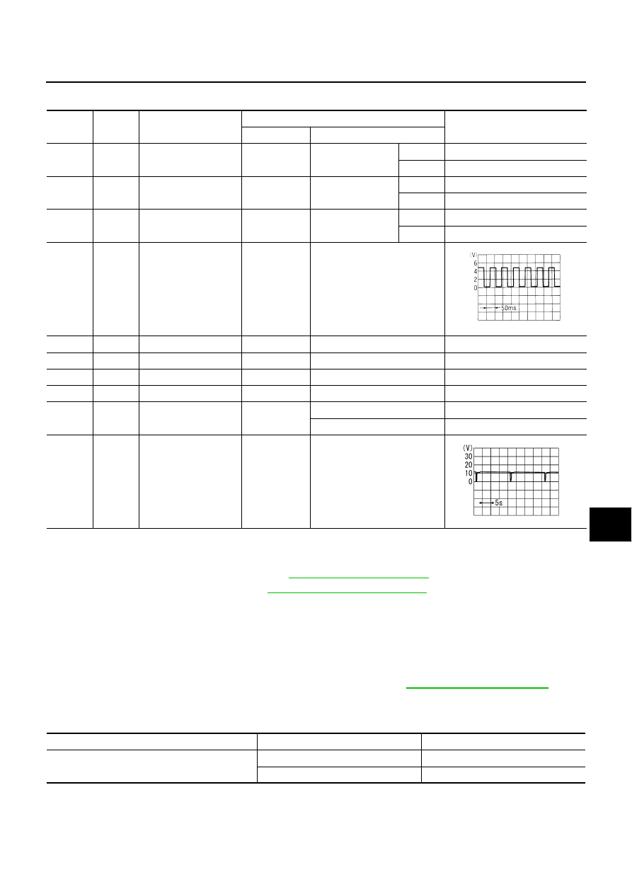
Terminal
No.
Wire
color
Item
Measuring condition
Reference value
Ignition switch
Operation or condition
4
P
Washer switch signal
ON
Wiper switch
WASH
Approx. 0 V
OFF
Battery voltage
9
OR
Wiper switch INT signal
ON
Wiper switch
INT
Approx. 0 V
OFF
Approx. 8 V
48
R/G
Intermittent wiper
volume signal
ON
Wiper intermittent
interval
Long
Approx. 3.6 V
Short
Approx. 0 V
49
PU/W
Vehicle speed signal
(2-pulse)
ON
Vehicle speed approx. 40 km/h
(25 MPH)
56
B
Ground
ON
-
Approx. 0 V
68
W/B
Ignition on signal
ON
-
Battery voltage
105
Y/L
Battery power supply
OFF
-
Battery voltage
113
B
Ground
ON
-
Approx. 0 V
124
SB
Wiper auto
stop signal
ON
Wiper is moving.
Approx. 0 V
Wiper is stopped.
Battery voltage
128
R/Y
Wiper motor
operation signal
ON
Wiper switch: INT position
ELF1080D
SKIA3507E
Setting change mode
CONSULT-ll (WORK SUPPORT)
Description
Wiper intermittent speed control by vehicle speed
ON
Activated
OFF
Disactivated