Infiniti M45 (Y34). Manual - part 673


  Index      Infiniti     Infiniti M45 (Y34) - service repair manual 2004 year


Search            copyright infringement  


Content   ..  671  672  673  674   ..


Infiniti M45 (Y34). Manual - part 673


OIL FILTER

LU-9

C

D

E

F

G

H

I

J

K

L

M

A

LU

OIL FILTER

PFP:15208

Removal and Installation

ABS000MD

REMOVAL

1.

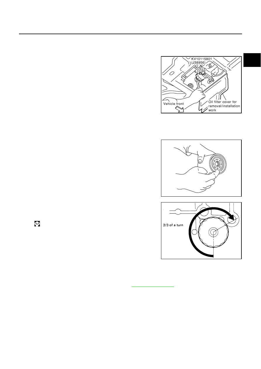
Open oil filter cover for removal/installation work on engine
undercover.

2.

Using the oil filter wrench (SST), remove the oil filter.

CAUTION:

Oil filter is provided with a relief valve.
Use genuine NISSAN oil filter or equivalent.

Be careful not to get burned when engine and engine oil are
hot.

When removing, prepare a shop cloth to absorb any engine
oil leakage or spillage.

Do not allow engine oil to adhere to drive belts.

Completely wipe off any engine oil that adhere to engine and vehicle.

INSTALLATION

1.

Remove foreign materials adhering to the oil filter installation surface.

2.

Apply engine oil to the oil seal circumference of new oil filter.

3.

Screw oil filter manually until it touches the installation surface,
then tighten it by 2/3 turn. Or tighten to specification.

INSPECTION AFTER INSTALLATION

1.

After warming up engine, check for engine oil leakage.

2.

Stop engine and wait for 15 minutes.

3.

Check engine oil level and add engine oil. Refer to 

LU-6, "ENGINE OIL"

 .

PBIC0137E

SMA010

Oil filter:

 :14.7 - 20.6 N·m (1.5 - 2.1 kg-m, 11 - 15 ft-lb)

SMA229B

LU-10

OIL PUMP

OIL PUMP

PFP:15010

Removal and Installation

ABS000ME

REMOVAL

1.

Remove front cover.
Refer to 

EM-38, "Removal and Installation"

 . 

2.

Remove oil pump drive spacer.

Set bolts in the two bolts holes [M6 x 1.0 mm (0.039 in)] on
the front surface. Using a small puller, remove oil pump drive
spacer from crankshaft.

NOTE:
The dimension between the centers of the two bolt holes is 33
mm (1.30 in).
In the figure, the commercial steering puller is used.

3.

Remove oil pump.

INSTALLATION

1.

Install oil pump.

2.

Install oil pump drive spacer as follows.

a.

When inserting oil pump drive spacer, align the crankshaft key
and the flat face of inner rotor.

If they are not aligned, rotate inner rotor by hand.

b.

Make sure that the each part is aligned. Using a tool such as a
plastic hammer, tap lightly until it reaches the end.

3.

Install in the reverse order of removal.

INSPECTION AFTER INSTALLATION

Start engine, and check there is no leak of engine oil.

Check level of engine oil, and add engine oil. Refer to 

LU-6, "ENGINE OIL"

 .

1.

Oil pump body

2.

Outer rotor

3.

Inner rotor

4.

Oil pump cover

5.

Oil pump drive spacer

6.

Regulator valve

7.

Regulator spring

8.

Regulator plug

PBIC0994E

PBIC0054E

PBIC0058E

OIL PUMP

LU-11

C

D

E

F

G

H

I

J

K

L

M

A

LU

Disassembly and Assembly

ABS000MF

DISASSEMBLY

1.

Remove oil pump cover.

2.

Remove inner rotor and outer rotor from oil pump body. 

3.

After removing regulator plug, remove regulator spring and regulator valve.

INSPECTION AFTER DISASSEMBLY 
Clearance of Oil Pump Parts

Measure clearance with feeler gauge.
Clearance between outer rotor and oil pump body (position 1)

Tip clearance between inner rotor and outer rotor (position 2)

Measure clearance with feeler gauge and straightedge.
Side clearance between inner rotor and oil pump body (position
3)

       Side clearance between outer rotor and oil pump body (posi-
tion 
       4)

Calculate the clearance between inner rotor and oil pump body
as follows.

Measure the outer diameter of protruded portion of inner rotor
(Position 5)

Measure the inner diameter of oil pump body with inside
micrometer (Position 6)

(Clearance) = (Inner diameter of oil pump body) – (Outer diame-
ter of inner rotor)

If out of the standard, replace oil pump assembly.

Standard

: 0.114 - 0.200 mm (0.0045 - 0.0079 in)

Standard

: Below 0.180 mm (0.0071in)

PBIC0139E

Standard

: 0.030 - 0.070 mm (0.0012 - 0.0028 in)

Standard

: 0.030 - 0.090 mm (0.0012 - 0.0035 in)

PBIC0140E

PBIC0141E

Standard

: 0.045 - 0.091 mm (0.0018 - 0.0036 in)

PBIC0142E

LU-12

OIL PUMP

Regulator Valve Clearance

(Clearance) = D1 (Valve hole diameter) – D2 (Outer diameter of
valve)

If out of the standard, replace oil pump assembly.

CAUTION:

Coat regulator valve with engine oil.

Check that it falls smoothly into the regulator valve hole by
its own weight.

ASSEMBLY

Installation is in the reverse order of removal.

Install inner rotor and outer rotor with the punched marks on the
oil pump cover side.

Standard

: 0.040 - 0.097 mm (0.0016 - 0.0038 in)

PBIC0143E

PBIC0144E


Content   ..  671  672  673  674   ..