Infiniti M45 (Y34). Manual - part 111
ON-VEHICLE SERVICE
AT-329
D
E
F
G
H
I
J
K
L
M
A
B
AT
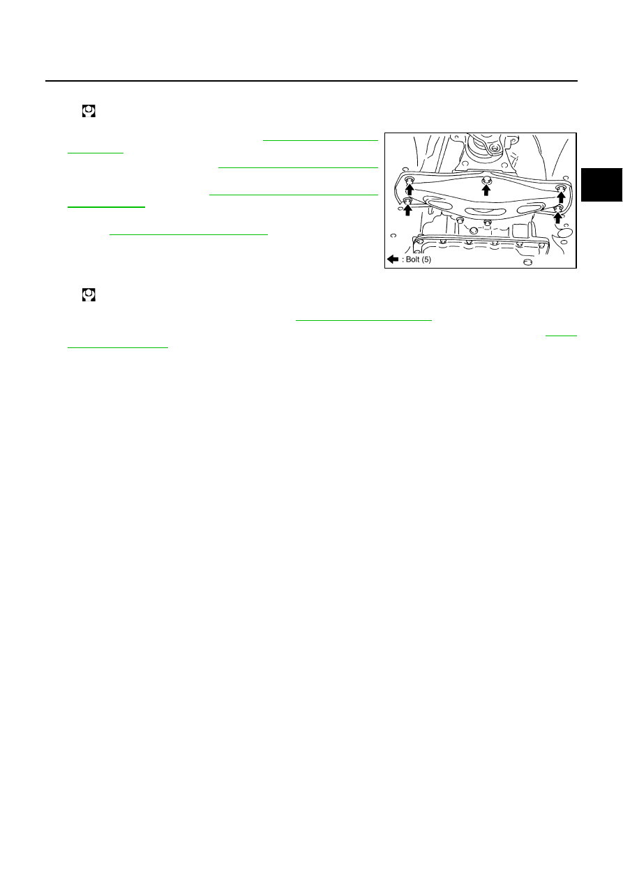
7.
Install engine rear member. Refer to
.
8.
Install propeller shaft. Refer to
PR-5, "Removal and Installation"
.
9.
AT-304, "Control Device Removal
10. Install exhaust front tube and center muffler with a power tool.
Refer to
EX-3, "Removal and Installation"
11. Install drain plug in oil pan.
CAUTION:
Do not reuse drain plug gasket.
12. Pour ATF into transmission assembly. Refer to
●
After completing installation, check fluid leakage and fluid level of transmission assembly. Refer to
Self-sealing bolt:
: 61 N·m (6.2 kg-m, 45 ft-lb)
: 34 N·m (3.5 kg-m, 25 ft-lb)
SCIA3703E