Infiniti M35/M45 Y50. Manual - part 974
PDU (POWER DISTRIBUTION UNIT)
PG-41
C
D
E
F
G
H
I
J
L
M
A
B
PG
Check Push-Button Ignition Switch (Indicator Circuit) System
NKS004EN
1.
CHECK PUSH-BUTTON IGNITION SWITCH INDICATOR SYSTEM
1.
Turn ignition switch OFF.
2.
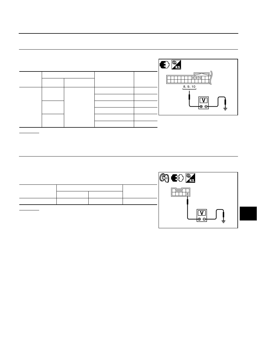
Check voltage between Intelligent Key unit connector and
ground.
OK or NG
OK
>> GO TO 2.
NG
>> Repair or replace push-button ignition switch.
2.
PUSH-BUTTON IGNITION SWITCH INDICATOR POWER SUPPLY SIGNAL
1.
Turn ignition switch OFF.
2.
Disconnect push-button ignition switch.
3.
Check voltage between push-button ignition switch connector
and ground.
OK or NG
OK
>> GO TO 3.
NG
>> Repair or replace push-button ignition switch.
Intelligent
Key unit
connector
Terminal
Push-button ignition
switch condition
Voltage (V)
(Approx)
(+)
(-)
M32
8
Ground part of
push-button
ignition switch
LOCK position
0
Except LOCK position
1.2
9
ACC position
0
Except ACC position
1.2
10
ON position
0
Except ON position
1.2
PIIB6121E
Push-button ignition
switch connector
Terminal
Voltage (V)
(Approx)
(+)
(-)
M27
8
Ground
Battery voltage
PIIB6122E