Infiniti M35/M45 Y50. Manual - part 950
OIL PUMP
LU-31
[VK45DE]
C
D
E
F
G
H
I
J
K
L
M
A
LU
OIL PUMP
PFP:15010
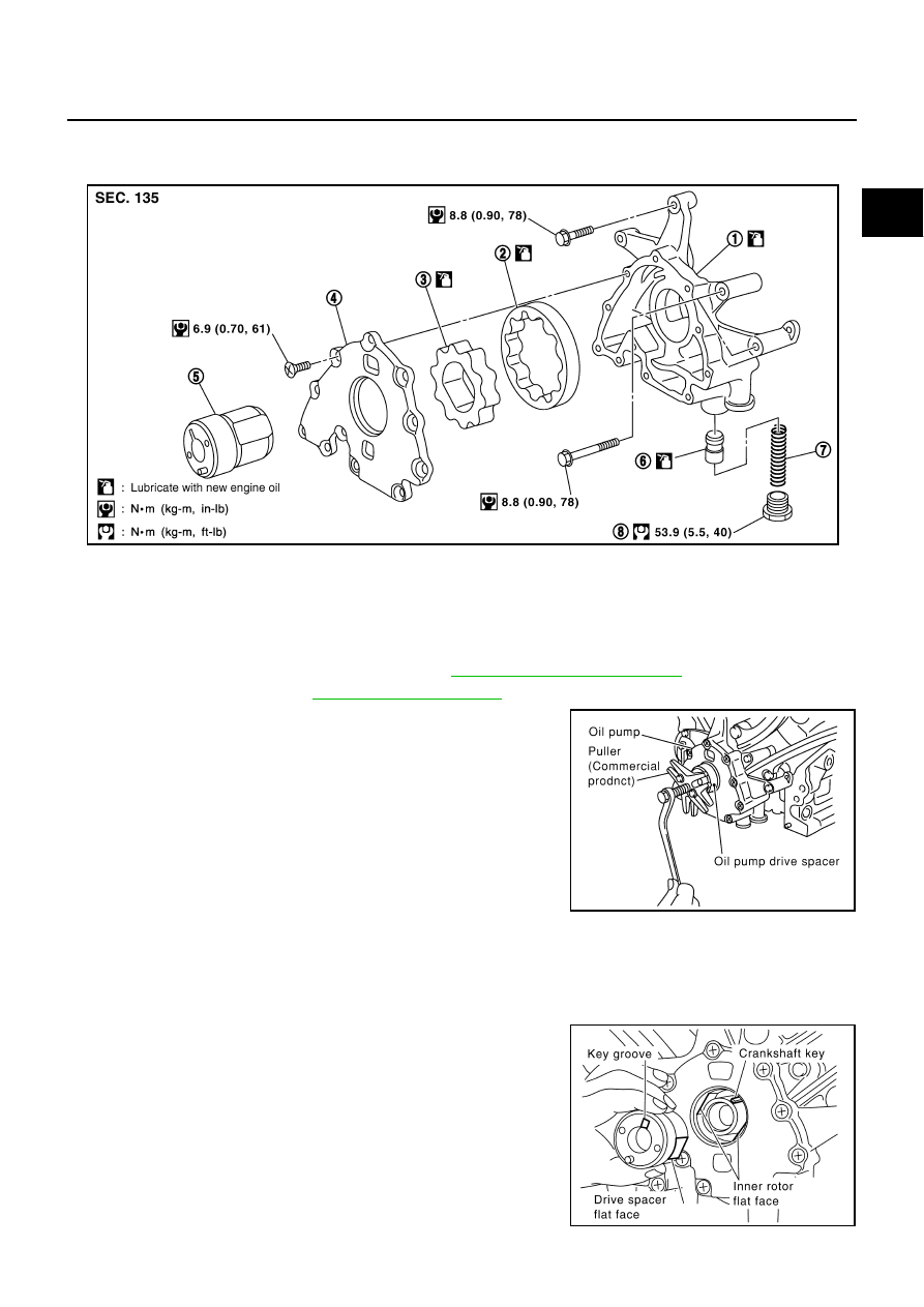
Components
NBS004QF
Removal and Installation
NBS004QG
REMOVAL
1.
Remove engine assembly from vehicle. Refer to
2.
3.
Remove oil pump drive spacer.
●
Set bolts in the two bolt holes [M6
×
pitch 1.0 mm (0.04 in)] on
the front surface. Using suitable puller, pull oil pump drive
spacer off from crankshaft.
NOTE:
The dimension between the centers of the two bolt holes is 33
mm (1.30 in).
In the figure, a commercial steering puller is used.
4.
Remove oil pump.
INSTALLATION
1.
Install the oil pump.
2.
Install oil pump drive spacer as follows:
a.
Insert oil pump drive spacer according to the directions of crank-
shaft key and the two flat surfaces of oil pump inner rotor.
●
If the positional relationship does not allow the insertion,
rotate oil pump inner rotor with a finger to allow spacer.
b.
After confirming that the position of each part is in correct condi-
tion to allow for spacer, force fit spacer by lightly tapping with
plastic hammer until it contacts and does not go further.
1.
Oil pump body
2.
Oil pump outer rotor
3.
Oil pump inner rotor
4.
Oil pump cover
5.
Oil pump drive spacer
6.
Regulator valve
7.
Regulator valve spring
8.
Regulator valve plug
PBIC1592E
PBIC0054E
PBIC0058E