Index Infiniti Infiniti M35/M45 Y50 - service repair manual 2007 year
Search copyright infringement
Content .. 912 913 914 915 ..
Infiniti M35/M45 Y50. Manual - part 914
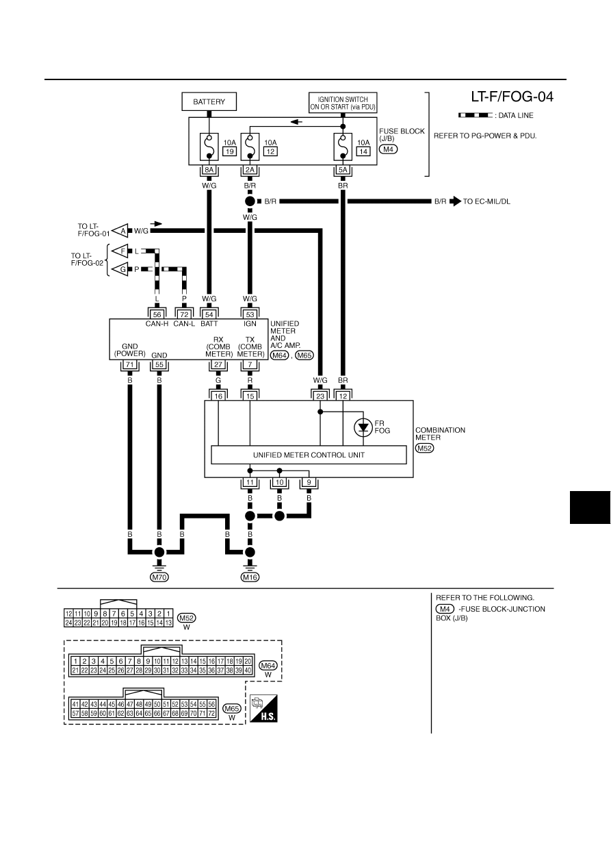
FRONT FOG LAMP
LT-201
C
D
E
F
G
H
I
J
L
M
A
B
LT
TKWT4854E