Infiniti M35/M45 Y50. Manual - part 829


  Index      Infiniti     Infiniti M35/M45 Y50 - service repair manual 2007 year


Search            copyright infringement  


Content   ..  827  828  829  830   ..


Infiniti M35/M45 Y50. Manual - part 829


REVERSE INTERLOCK DOOR MIRROR SYSTEM

GW-113

C

D

E

F

G

H

J

K

L

M

A

B

GW

3. 

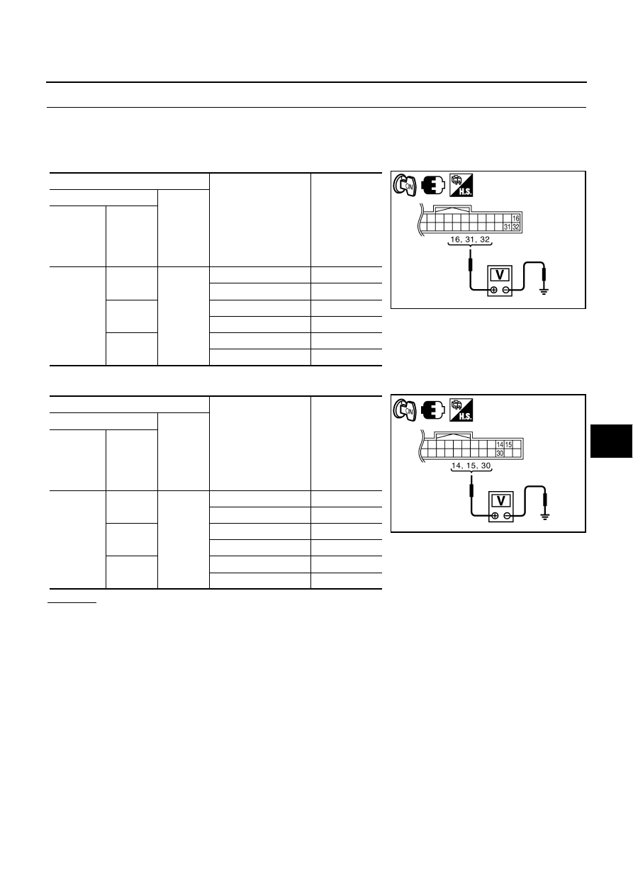
CHECK AUTOMATIC DRIVE POSITIONER CONTROL UNIT OUTPUT SIGNAL

1.

Connect automatic drive positioner control unit connector.

2.

Turn ignition switch ON.

3.

[Door mirror LH]
Check voltage between automatic drive positioner control unit connector and ground.

4.

[Door mirror RH]
Check voltage between automatic drive positioner control unit connector and ground.

OK or NG

OK

>> Replace malfunction door mirror actuator.

NG

>> Replace automatic drive positioner control unit.

Terminals

Mirror switch condition

Voltage (V)

(Approx.)

(+)

(-)

Automatic 

drive posi-

tioner con-

trol unit 

connector

Terminal

M6

16

Ground

DOWN / RIGHT

Battery voltage

Other than above

0

31

UP

Battery voltage

Other than above

0

32

LEFT

Battery voltage

Other than above

0

Terminals

Mirror switch condition

Voltage (V)

(Approx.)

(+)

(-)

Automatic 

drive posi-

tioner con-

trol unit 

connector

Terminal

M6

14

Ground

UP

Battery voltage

Other than above

0

15

LEFT

Battery voltage

Other than above

0

30

DOWN / RIGHT

Battery voltage

Other than above

0

PIIB6025E

PIIB6026E

GW-114

REVERSE INTERLOCK DOOR MIRROR SYSTEM

Check Mirror Sensor Circuit 

NIS0023E

1. 

CHECK MIRROR SENSOR INSPECTION

 With CONSULT-II

Check the voltage on  (MIR/SE LH R–L, MIR/SE LH U–D, MIR/SE RH R–L, MIR/SE RH U–D) in the DATA
MONITOR.

 Without CONSULT-II

1.

Turn ignition switch ON.

2.

Check voltage between automatic drive positioner control unit connector and ground.

OK or NG

OK

>> Mirror sensor LH circuit is OK.

NG

>> GO TO 3.

2. 

CHECK MIRROR SENSOR POWER SUPPLY 1

Check voltage between door mirror connector and ground.

OK or NG

OK

>> GO TO 5.

NG

>> GO TO 3.

Monitor item

 [OPERATION or UNIT]

Contents

MIR/SE LH R–L

“V”

Voltage output from door mirror LH horizontal sensor 
(LH/RH) is displayed.

MIR/SE LH U–D

“V”

Voltage output from door mirror LH vertical sensor 
(UP/DOWN) is displayed.

MIR/SE RH R–L

“V”

Voltage output from door mirror RH horizontal sensor 
(LH/RH) is displayed.

MIR/SE RH U–D

“V”

Voltage output from door mirror RH vertical sensor 
(UP/DOWN) is displayed.

PIIA0197E

Terminals

Mirror face position

Voltage (V)

(Approx.)

(+)

(-)

Automatic drive 

positioner control 

unit connector

Terminal

M6

Door 

mirror 

RH side

5

Ground

Close to perk

4.2

Close to valley

0.5

21

Close to left edge

3.5

Close to right edge

0.5

Door 

mirror 

LH side

6

Close to perk

4.2

Close to valley

0.5

22

Close to left edge

0.5

Close to right edge

3.5

PIIB6027E

Terminals

Voltage (V)

(Approx.)

(+)

(-)

Door mirror 

connector

Terminal

D2 (LH)

D39 (RH)

11

Ground

Battery voltage

PIIB6032E

REVERSE INTERLOCK DOOR MIRROR SYSTEM

GW-115

C

D

E

F

G

H

J

K

L

M

A

B

GW

3. 

CHECK MIRROR SENSOR POWER SUPPLY 2

1.

Turn ignition switch OFF.

2.

Disconnect door mirror connector.

3.

Turn ignition switch ON.

4.

Check voltage between automatic drive positioner control unit connector and ground.

OK or NG

OK

>> GO TO 4.

NG

>> Replace automatic drive positioner control unit.

4. 

CHECK HARNESS CONTINUITY 1

1.

Turn ignition switch OFF.

2.

Disconnect automatic drive positioner control unit connector.

3.

Check continuity between automatic drive positioner control unit connector and door mirror connector.

4.

Check continuity between automatic drive positioner control unit
connector and ground.

OK or NG

OK

>> Check the condition of harness and connector.

NG

>> Repair or replace harness.

Terminals

Voltage (V)

(Approx.)

(+)

(-)

Automatic drive 

positioner control 

unit connector

Terminal

M7

33

Ground

Battery voltage

PIIB6028E

A

B

Continuity

Automatic 

drive posi-

tioner control 

unit connector

Terminal

Door mirror  

connector

Terminal

M7

33

D2 (LH)

D39 (RH)

11

Yes

A

Ground

Continuity

Automatic drive 

positioner control 

unit connector

Terminal

M7

33

No

PIIB6033E

GW-116

REVERSE INTERLOCK DOOR MIRROR SYSTEM

5. 

CHECK MIRROR SENSOR GROUND 1

1.

Turn ignition switch OFF.

2.

Disconnect door mirror connector.

3.

Check continuity between door mirror connector and ground.

OK or NG

OK

>> GO TO 8.

NG

>> GO TO 6.

6. 

CHECK MIRROR SENSOR GROUND 2

Check continuity between automatic drive positioner control unit connector and ground.

OK or NG

OK

>> GO TO 7.

NG

>> Replace auto drive positioner control unit.

7. 

CHECK HARNESS CONTINUITY 2

1.

Disconnect automatic drive positioner control unit connector.

2.

Check continuity between automatic drive positioner control unit connector and door mirror connector.

3.

Check continuity between automatic drive positioner control unit
connector and door mirror connector.

OK or NG

OK

>> Check the condition of the harness and connector.

NG

>> Repair or replace harness between automatic drive positioner control unit and door mirror.

Door mirror connector

Terminal

Ground

Continuity

D2 (LH)

D39 (RH)

12

Yes

PIIB6034E

Automatic drive posi-

tioner control unit con-

nector

Terminal

Ground

Continuity

M7

41

Yes

PIIB6029E

A

B

Continuity

Automatic 

drive posi-

tioner control 

unit connector

Terminal

Door mirror  

connector

Terminal

M7

41

D2 (LH)

D39 (RH)

12

Yes

A

Ground

Continuity

Automatic drive 

positioner control 

unit connector

Terminal

M7

41

Yes

PIIB6035E


Content   ..  827  828  829  830   ..