Infiniti M35/M45 Y50. Manual - part 827


  Index      Infiniti     Infiniti M35/M45 Y50 - service repair manual 2007 year


Search            copyright infringement  


Content   ..  825  826  827  828   ..


Infiniti M35/M45 Y50. Manual - part 827


REVERSE INTERLOCK DOOR MIRROR SYSTEM

GW-105

C

D

E

F

G

H

J

K

L

M

A

B

GW

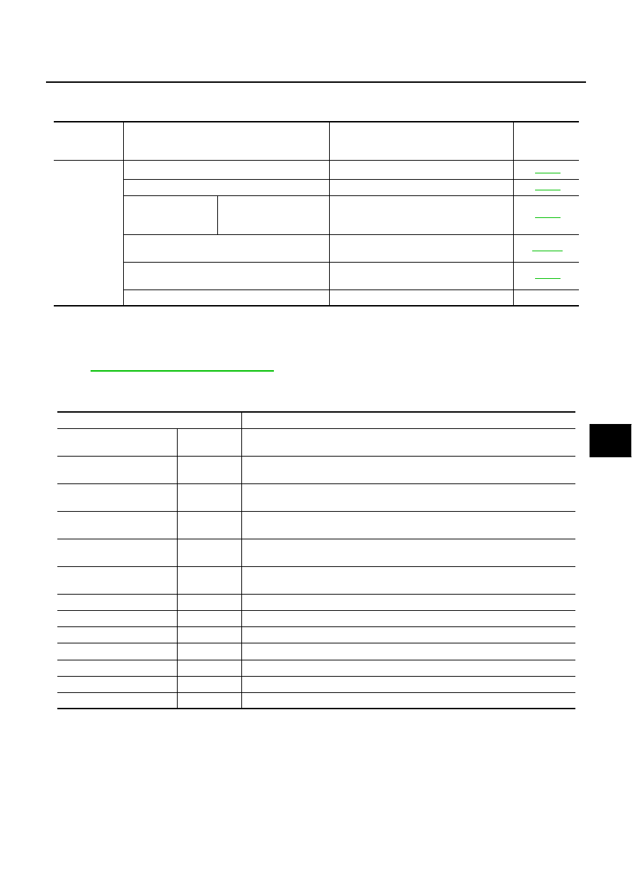
CONSULT-II Function (AUTO DRIVE POS.)

NIS00238

CONSULT-II can display each diagnostic item using the diagnostic test modes shown following.

*1: For setting automatic drive positioner functions only.
*2: During vehicle driving, do not perform active test.

CONSULT-II START PROCEDURE

Refer to 

GI-38, "CONSULT-II Start Procedure"

DATA MONITOR
Selection from Menu

ACTIVE TEST

CAUTION:

During vehicle driving, do not perform active test.

NOTE:
If active test is performed, reset seat memory and key fob interlock drive positioner after performing work.

CONSULT-II 

diagnosis 

items

Inspection item, self-diagnosis mode

Content

Refer to page

AUTO DRIVE
POSITIONER

WORK SUPPORT*

1

Changes the setting for each function.

SE-39

SELF–DIG RESULTS

Check the self-diagnosis results.

SE-37

DATA MONITOR

Selection from menu

Displays the input data to driver seat control 
unit and automatic driving positioned control 
unit on real-time basis.

SE-38

CAN DIAGNOSTIC SUPPORT MONITOR

The results of transmit / receive diagnosis of 
CAN communication can be read

LAN-13

ACTIVE TEST

*2

Gives a drive signal to a load to check the 
operation.

SE-39

DRIVER SEAT CONTROL UNIT PART NUMBER

Displays driver seat control unit part No.

Monitor item [OPERATION or UNIT]

Contents

MIR CON SW–UP

“ON/OFF”

ON/OFF status judged from the door mirror remote control switch (UP) signal is 
displayed.

MIR CON SW–DN

“ON/OFF”

ON/OFF status judged from the door mirror remote control switch (DOWN) signal 
is displayed.

MIR CON SW–RH

“ON/OFF”

ON/OFF status judged from the door mirror remote control switch (RIGHT) signal 
is displayed.

MIR CON SW–LH

“ON/OFF”

ON/OFF status judged from the door mirror remote control switch (LEFT) signal s 
displayed.

MIR CHNG SW–R

“ON/OFF”

ON/OFF status judged from the door mirror remote control switch (switching to 
RIGHT) signal is displayed.

MIR CHNG SW–L

“ON/OFF”

ON/OFF status judged from the door mirror remote control switch (switching to 
LEFT) signal is displayed.

SET SW

“ON/OFF”

ON/OFF status judged from the setting switch signal is displayed.

MEMORY SW1

“ON/OFF”

ON/OFF status judged from the seat memory switch 1 signal is displayed.

MEMORY SW2

“ON/OFF”

ON/OFF status judged from the seat memory switch 2 signal is displayed.

MIR/SE RH R–L

“V”

Voltage output from RH door mirror sensor (LH/RH) is displayed.

MIR/SE RH U–D

“V”

Voltage output from RH door mirror sensor (UP/DOWN) is displayed.

MIR/SE LH R–L

“V”

Voltage output from LH door mirror sensor (LH/RH) is displayed.

MIR/SE LH U–D

“V”

Voltage output from LH door mirror sensor (UP/DOWN) is displayed.

GW-106

REVERSE INTERLOCK DOOR MIRROR SYSTEM

Display Item List

Work Flow 

NIS00239

1.

Check the symptom and customer's requests.

2.

Understand the system description. Refer to 

GW-94, "System Description"

 .

3.

According to the trouble diagnosis chart, repair or replace the cause of the malfunction. Refer to 

GW-106,

"Symptom Chart"

4.

Does reverse interlock door mirror system operate normally?
Yes , GO TO 5.
No, GO TO 3.

5.

INSPECTION END

Symptom Chart

NIS0023A

Test item

Description

MIRROR MOTOR RH

The RH mirror motor moves the mirror UP/DOWN and LEFT/RIGHT by receiving the drive 
signal.

MIRROR MOTOR LH

The LH mirror motor moves the mirror UP/DOWN and LEFT/RIGHT by receiving the drive 
signal.

Symptom

Diagnoses / service procedure

Reference 

page

Reverse interlock door mirror does not operate.

1. Check seat set switch circuit

SE-81

2. Check changeover switch circuit

GW-107

3. Check mirror switch circuit

GW-109

4. Check A/T control device R position signal circuit

GW-117

5. Check mirror motor circuit

GW-111

6. Check mirror sensor circuit

GW-114

7. Replace automatic drive positioner control unit

SE-11

At reverse interlock  door mirror system operation, mirror 
angle is not in the setting position

After finishing the reverse interlock door mirror system. 
Operation, mirror angle does not return to the original posi-
tion

1. Check mirror sensor circuit

GW-114

2. Check A/T control device R position signal circuit

GW-117

3. Replace automatic drive positioner control unit

SE-11

None of the door mirror can be operated using mirror switch.

Check mirror switch circuit

GW-109

A part of the remote control door mirror does not operated.

1. Check mirror switch circuit

GW-109

2. Check door mirror circuit

GW-109

Mirror remote control switch can not be switched right and left.

1. Check changeover switch circuit

GW-107

2. Check mirror switch circuit

GW-109

REVERSE INTERLOCK DOOR MIRROR SYSTEM

GW-107

C

D

E

F

G

H

J

K

L

M

A

B

GW

Check Changeover Switch Circuit

NIS0023B

1. 

CHECK CHANGEOVER SWITCH SIGNAL

 With CONSULT-II

Check the operation on (MIR CHNG SW-R” or “MIR CHNG SW-L) in the DATA MONITOR.

 Without CONSULT-II

1.

Turn ignition switch ON.

2.

Check voltage between automatic drive positioner control unit connector and ground.

OK or NG

OK

>> Changeover switch circuit is OK.

NG

>> GO TO 2.

Monitor item

 [OPERATION or UNIT]

Contents

MIR CHNG SW–R

“ON/

OFF”

ON/OFF status judged from the changeover 
switch (switching to RIGHT) signal is displayed.

MIR CHNG SW–L

“ON/

OFF”

ON/OFF status judged from the changeover 
switch (switching to LEFT) signal is displayed.

PIIA0191E

Terminals

Change over switch 

condition

Voltage (V)

(Approx.)

(+)

(-)

Automatic 

drive posi-

tioner con-

trol unit 

connector

Terminal

M6

2

Ground

RIGHT

0

Other than above

5

18

LEFT

0

Other than above

5

PIIB6015E

GW-108

REVERSE INTERLOCK DOOR MIRROR SYSTEM

2. 

CHECK HARNESS CONTINUITY

1.

Turn ignition switch OFF.

2.

Disconnect automatic drive positioner control unit and door mirror remote control switch connector.

3.

Check continuity between automatic drive positioner control unit connector and door mirror remote control
switch connector.

4.

Check continuity between automatic drive positioner control unit
connector and ground.

OK or NG

OK

>> GO TO 3.

NG

>> Repair or replace harness.

3. 

CHECK CANGEOVER SWITCH 

Check door mirror remote control switch.

OK or NG

OK

>> GO TO 4.

NG

>> Replace door mirror remote control switch.

4. 

CHECK DOOR MIRROR REMOTE CONTROL SWITCH GROUND CIRCUIT

Check continuity between door mirror remote control switch connector and ground.

OK or NG

OK

>> GO TO 5.

NG

>> Repair or replace harness.

A

B

Continuity

Automatic 

drive posi-

tioner control 

unit connector

Terminal

Door mirror 

remote control 

switch 

connector

Terminal

M6

2

M95

3

Yes

18

2

A

Ground

Continuity

Automatic drive 

positioner control 

unit connector

Terminal

No

M6

2

18

PIIB6016E

Terminal

Change over switch 

condition

Continuity

Door mirror remote control switch

2

13

LEFT

Yes

Other than above

No

3

RIGHT

Yes

Other than above

No

PIIB6017E

Door mirror remote 

control switch connector

Terminal

Ground

Continuity

M95

13

Yes

PIIB6018E


Content   ..  825  826  827  828   ..