Infiniti M35/M45 Y50. Manual - part 778


  Index      Infiniti     Infiniti M35/M45 Y50 - service repair manual 2007 year


Search            copyright infringement  


Content   ..  776  777  778  779   ..


Infiniti M35/M45 Y50. Manual - part 778


FRONT SUSPENSION ASSEMBLY

FSU-9

[2WD]

C

D

F

G

H

I

J

K

L

M

A

B

FSU

.

Removal and Installation 

NES000ID

REMOVAL

1.

For VK45DE engine models, disconnect related electric wires and hoses from engine assembly to remove
front suspension member with engine assembly. Refer to 

EM-247, "ENGINE ASSEMBLY"

 .

2.

Remove cowl top panel and hood. Refer to 

EI-18, "COWL TOP"

 , 

EI-17, "HOOD"

 .

3.

For VQ35DE engine models, install engine slinger, and then hoist engine. Refer to 

EM-114, "Removal and

Installation (2WD Models)"

 .

4.

Remove tires from vehicle with a power tool.

5.

Remove wheel sensor from steering knuckle. Refer to 

BRC-54, "WHEEL SENSOR"

 .

CAUTION:

Do not pull on wheel sensor harness.

6.

Remove brake hose bracket. Refer to 

BR-11, "BRAKE TUBE AND HOSE"

 .

7.

Remove undercover with a power tool.

8.

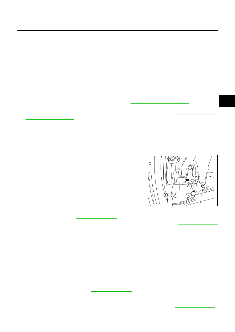
Remove cotter pin (1), and then loosen the nut.

9.

Remove steering outer socket (2) from steering knuckle (3) so
as not to damage ball joint boot (4) using the ball joint remover
(suitable tool).

CAUTION:

Temporarily tighten the nut to prevent damage to threads
and to prevent the ball joint remover (suitable tool) from
suddenly coming off.

10. Remove the mounting nut on the upper side of stabilizer con-

necting rod with a power tool, and then remove stabilizer con-
necting rod from transverse link.

11. Separate steering gear assembly and lower joint. Refer to 

PS-13, "STEERING COLUMN"

 .

12. Remove rack stay. Refer to 

FSU-8, "Components"

 .

13. Remove steering hydraulic piping bracket from front suspension member. Refer to 

PS-39, "HYDRAULIC

LINE"

 .

14. Remove the mounting nut and bolt on the lower side of shock absorber with a power tool, and then

remove shock absorber from transverse link.

15. Remove cotter pin of transverse link and steering knuckle, and then loosen nut.

16. Set jack under front suspension member.

17. Remove transverse link from steering knuckle so as not to damage ball joint boot using the ball joint

remover (suitable tool)

CAUTION:

Temporarily tighten the nut to prevent damage to threads and to prevent ball joint remover (suit-
able tool) from suddenly coming off.

18. Remove the mounting nuts of engine mounting insulator. Refer to 

EM-114, "ENGINE ASSEMBLY"

 .

19. Remove the mounting bolts of member bracket, and then remove member bracket from front suspension

member with a power tool. Refer to 

FSU-8, "Components"

 .

20. Remove the mounting nut and bolts of member stay, and then remove member stay from front suspension

member and vehicle with a power tool.

21. Remove the mounting nut of front suspension member with a power tool. Refer to 

FSU-8, "Components"

 .

1.

Shock absorber mounting bracket

2.

Bound bumper

3.

Rubber seat

4.

Coil spring

5.

Shock absorber 

6.

Upper link

7.

Steering knuckle

8.

Transverse link

9.

Washer

10. Steering stopper bracket

11. Stabilizer connecting rod

12. Stabilizer bar

13. Stabilizer bushing

14. Stabilizer clamp

15. Front suspension member

16. Rack stay

17. Member stay

18. Member bracket

19. Clamp

20. Cotter pin

21. Stopper rubber

Refer to 

GI-11, "Components"

 , for the symbols in the figure.

SGIA1183E

FSU-10

[2WD]

FRONT SUSPENSION ASSEMBLY

22. For VQ35DE engine models, gradually lower a jack to remove front suspension assembly from vehicle.

For VK45DE engine models, gradually lower a jack to remove front suspension assembly with engine
assembly from vehicle.

INSTALLATION

Installation is the reverse order of removal. For tightening torque, refer to 

FSU-8, "Components"

 .

Perform final tightening of each of parts (rubber bushing), under unladen conditions, which were removed
when removing front suspension assembly. Check wheel alignment. Refer to 

FSU-6, "Wheel Alignment

Inspection"

 .

Adjust neutral position of steering angle sensor after checking wheel alignment. Refer to 

BRC-6, "Adjust-

ment of Steering Angle Sensor Neutral Position"

 .

Check wheel sensor harness for proper connection. Refer to 

BRC-54, "WHEEL SENSOR"

 .

COIL SPRING AND SHOCK ABSORBER

FSU-11

[2WD]

C

D

F

G

H

I

J

K

L

M

A

B

FSU

COIL SPRING AND SHOCK ABSORBER

PFP:55302

Removal and Installation

NES000IE

REMOVAL

1.

Remove tires from vehicle with a power tool.

2.

Remove harness of wheel sensor from shock absorber. Refer to 

BRC-54, "WHEEL SENSOR"

 .

CAUTION:

Do not pull on wheel sensor harness.

3.

Remove brake hose bracket. Refer to 

BR-11, "BRAKE TUBE AND HOSE"

 .

4.

Remove the mounting nut on the upper side of stabilizer connecting rod with a power tool, and then
remove stabilizer connecting rod from transverse link.

5.

Remove mounting nut and bolt on the lower side of shock absorber with a power tool, and then remove
shock absorber from transverse link.

6.

Remove cotter pin of transverse link and steering knuckle, and then loosen nut.

7.

Remove transverse link from steering knuckle so as not to damage ball joint boot using the ball joint
remover (suitable tool).

CAUTION:

Temporarily tighten the nut to prevent damage to threads and to prevent ball joint remover (suit-
able tool) from suddenly coming off.

8.

Remove the mounting nuts of shock absorber mounting bracket, then remove shock absorber from vehi-
cle.

INSTALLATION

Installation is the reverse order of removal. For tightening torque, refer to 

FSU-8, "Components"

 .

Perform final tightening of bolt and nut at the shock absorber lower side (rubber bushing), under unladen
conditions with tires on level ground. Check wheel alignment. Refer to 

FSU-6, "Wheel Alignment Inspec-

tion"

 .

Adjust neutral position of steering angle sensor after checking wheel alignment. Refer to 

BRC-6, "Adjust-

ment of Steering Angle Sensor Neutral Position"

 .

Check wheel sensor harness for proper connection. Refer to 

BRC-54, "WHEEL SENSOR"

 .

Disassembly and Assembly

NES000IF

DISASSEMBLY

CAUTION:

Do not damage shock absorber piston rod when removing components from shock absorber.

1.

Install strut attachment [SST] to shock absorber and secure it in
a vise.

CAUTION:

When installing the strut attachment to shock absorber,
wrap a shop cloth around strut to protect it from damage.

SEIA0296E

FSU-12

[2WD]

COIL SPRING AND SHOCK ABSORBER

2.

Using a spring compressor (commercial service tool), compress
coil spring between rubber seat and spring lower seat (on shock
absorber) until coil spring with a spring compressor is free.

CAUTION:

Be sure a spring compressor is securely attached coil
spring. Compress coil spring

3.

Make sure coil spring with a spring compressor between rubber
seat and spring lower seat (shock absorber) is free and then
remove piston rod lock nut while securing the piston rod tip so
that piston rod does not turn.

4.

Remove shock absorber mounting bracket, rubber seat, bound
bumper from shock absorber.

5.

Remove coil spring with a spring compressor, and then gradually release a spring compressor.

CAUTION:

Loosen while making sure coil spring attachment position does not move.

6.

Remove the strut attachment from shock absorber.

INSPECTION AFTER DISASSEMBLY
Shock Absorber Inspection

Check the following:

Shock absorber for deformation, cracks or damage, and replace it if a malfunction is detected.

Piston rod for damage, uneven wear or distortion, and replace it if a malfunction is detected.

For oil leakage, and replace it if a malfunction is detected. 

Shock Absorber Mounting Bracket and Rubber Parts Inspection

Check shock absorber mounting bracket for cracks and rubber parts for wear. Replace it if a malfunction is
detected.

Coil Spring Inspection

Check coil spring for cracks, wear or damage, and replace it if a malfunction is detected. 

ASSEMBLY

CAUTION:

Do not damage shock absorber piston rod when installing components to shock absorber.

1.

Install strut attachment [SST] to shock absorber and secure it in
a vise.

CAUTION:

When installing the strut attachment to shock absorber,
wrap a shop cloth around strut to protect it from damage.

2.

Compress coil spring using a spring compressor (commercial
service tool), and install it onto shock absorber.

SEIA0297E

SEIA0296E

SEIA0297E


Content   ..  776  777  778  779   ..