Infiniti M35/M45 Y50. Manual - part 777


  Index      Infiniti     Infiniti M35/M45 Y50 - service repair manual 2007 year


Search            copyright infringement  


Content   ..  775  776  777  778   ..


Infiniti M35/M45 Y50. Manual - part 777


NOISE, VIBRATION AND HARSHNESS (NVH) TROUBLESHOOTING

FSU-5

[2WD]

C

D

F

G

H

I

J

K

L

M

A

B

FSU

NOISE, VIBRATION AND HARSHNESS (NVH) TROUBLESHOOTING

PFP:00003

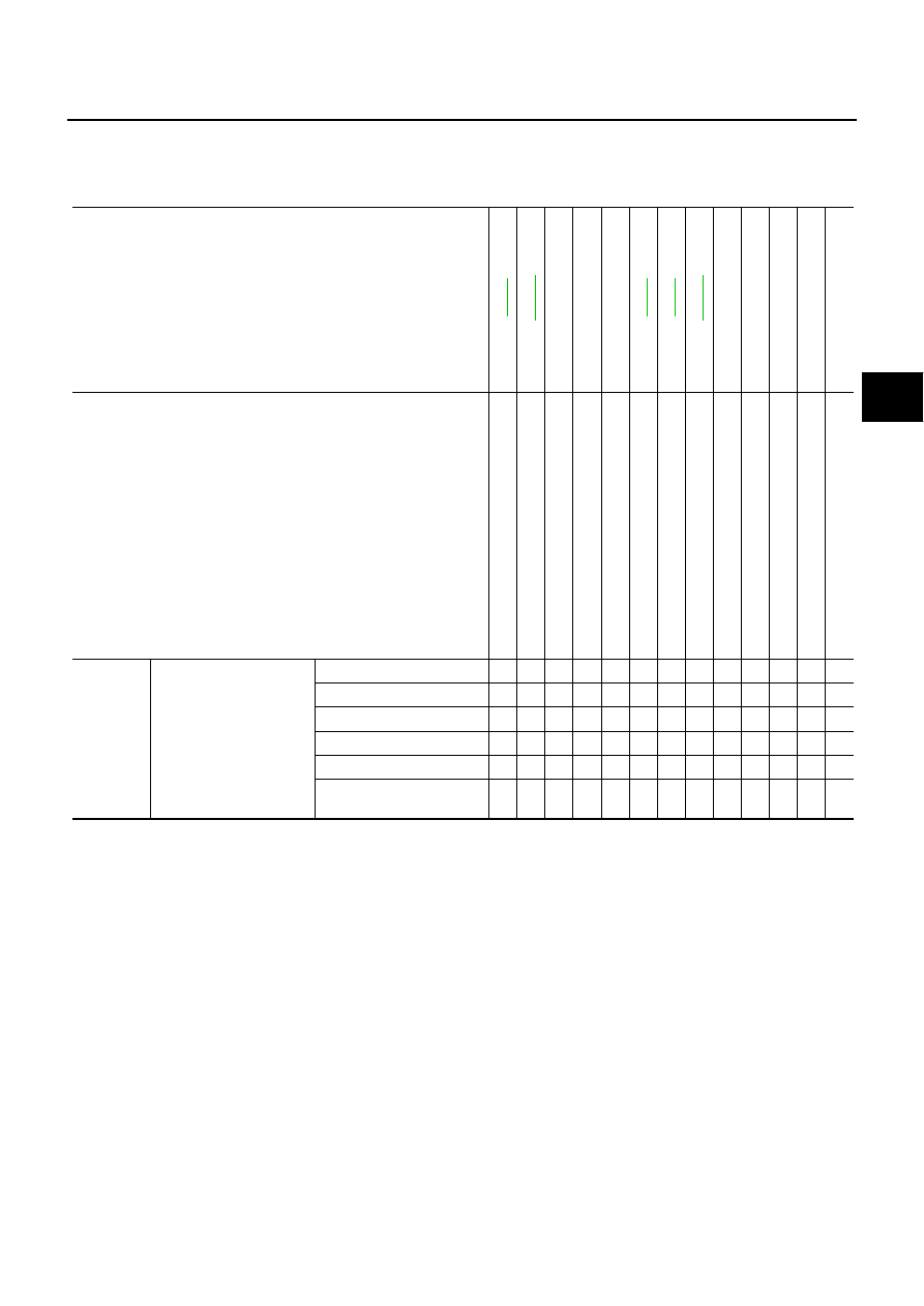
NVH Troubleshooting Chart

NES000I9

Use chart below to help you find the cause of the symptom. If necessary, repair or replace these parts.

×

: Applicable

Reference page

FSU-

8

FS

U

-1

2

FSU-

8

FSU-

6

FS

U

-1

8

NVH 

in

 PR s

e

c

tio

n

NVH 

in

 F

A

X

 a

n

d

 FSU s

e

c

ti

o

n

NVH i

n

 W

T

 s

e

c

tio

n

NVH 

in

 BR s

e

c

tio

n

NVH 

in

 PS s

e

c

tio

n

Possible cause and SUSPECTED PARTS

Im

pr

o

per

 i

n

st

al

la

ti

on

lo

osen

ess

S

tr

u

t d

e

fo

rm

at

ion,

 d

a

m

age 

or

 d

e

fl

ec

ti

on

Bus

h

ing or

 m

oun

ti

ng det

er

io

ra

ti

on

P

a

rt

s

 in

te

rf

e

re

n

c

e

Spr

ing f

a

ti

gue

Sus

pens

io

n l

o

o

s

ene

ss

In

co

rr

ect

 w

h

e

e

l al

ignm

en

t

S

ta

b

ili

z

er

 bar

 f

a

ti

g

u

e

PROPELL

E

R SHAF

T

FRONT AXLE AND FRO

N

T

 SUSPENSION

ROAD W

H

EEL

BRAKES

STEERING

Symptom

FRONT SUSPENSION

Noise

×

×

×

×

×

×

×

×

×

×

×

Shake

×

×

×

×

×

×

×

×

×

×

Vibration

×

×

×

×

×

×

×

×

Shimmy

×

×

×

×

×

×

×

×

×

Judder

×

×

×

×

×

×

×

Poor quality ride or han-
dling

×

×

×

×

×

×

×

×

×

FSU-6

[2WD]

FRONT SUSPENSION ASSEMBLY

FRONT SUSPENSION ASSEMBLY

PFP:54010

On-Vehicle Inspection 

NES000IA

Make sure the mounting conditions (looseness, back lash) of each component and component conditions
(wear, damage) are normal.

INSPECTION OF UPPER LINK BALL JOINT END PLAY

1.

Set front wheels in a straight-ahead position. Do not depress brake pedal.

2.

Place an iron bar or similar tool between transverse link and steering knuckle.

3.

Measure axial end play by prying it up and down.

CAUTION:

Be careful not to damage ball joint boot. Do not damage the installation position by applying
excessive force.

SHOCK ABSORBER INSPECTION

Check for oil leakage, damage and breakage of installation positions.

Wheel Alignment Inspection

NES000IB

DESCRIPTION

Measure wheel alignment under unladen conditions. 

NOTE:
“Unladen conditions” means that fuel, engine coolant, and lubricant are full. Spare tire, jack, hand tools and
mats are in designated positions.

PRELIMINARY CHECK

Check tires for improper air pressure and wear.

Check road wheels for runout. Refer to 

WT-6, "ROAD WHEEL"

 .

Check wheel bearing axial end play. Refer to 

FAX-5, "WHEEL BEARING INSPECTION"

 .

Check transverse link ball joint axial end play. Refer to 

FSU-14, "INSPECTION AFTER REMOVAL"

 .

Check shock absorber operation.

Check each mounting part of axle and suspension for looseness and deformation.

Check each of suspension member, shock absorber, upper link and transverse link for cracks, deforma-
tion and other damage.

Check vehicle height (posture).

GENERAL INFORMATION AND RECOMMENDATIONS

A four-wheel thrust alignment should be performed.

This type of alignment is recommended for any NISSAN/INFINITI vehicle.

The four-wheel “thrust” process helps ensure that the vehicle is properly aligned and the steering wheel is
centered.

The alignment rack itself should be capable of accepting any NISSAN/INFINITI vehicle.

The rack should be checked to ensure that it is level.

Make sure the machine is properly calibrated.

Your alignment equipment should be regularly calibrated in order to give correct information.

Check with the manufacturer of your specific equipment for their recommended Service/Calibration
Schedule.

Axial end play

: 0 mm (0 in)

FRONT SUSPENSION ASSEMBLY

FSU-7

[2WD]

C

D

F

G

H

I

J

K

L

M

A

B

FSU

THE ALIGNMENT PROCESS

IMPORTANT:
Use only the alignment specifications listed in this Service Manual.

When displaying the alignment settings, many alignment machines use “indicators”: (Green/red, plus or
minus, Go/No Go). Do NOT use these indicators.

The alignment specifications programmed into your machine that operate these indicators may not be cor-
rect.

This may result in an ERROR.

Some newer alignment machines are equipped with an optional “Rolling Compensation” method to “com-
pensate” the sensors (alignment targets or head units). DO NOT use this “Rolling Compensation”
method.

Use the “Jacking Compensation Method”. After installing the alignment targets or head units, raise the
vehicle and rotate the wheels 1/2 turn both ways.

See Instructions in the alignment machine you're using for more information on this.

INSPECTION OF CAMBER, CASTER AND KINGPIN INCLINATION ANGLES

Camber, caster, kingpin inclination angles cannot be adjusted.

Before inspection, mount front wheels onto turning radius gauge. Mount rear wheels onto a stand that has
same height so vehicle will remain horizontal.

Using a CCK Gauge

Install the CCK gauge attachment [SST: KV991040S0 (

)] with the following procedure on wheel, then

measure wheel alignment.

1.

Remove three wheel nuts, and install the guide bolts to hub bolt.

2.

Screw the adapter into the plate until it contacts the plate tightly.

3.

Screw the center plate into the plate.

4.

Insert the plate assembly on the guide bolt. Put the spring in,
and then evenly screw the three guide bolt nuts. When fastening
the guide nuts, do not completely compress the spring.

5.

Place the dent of alignment gauge onto the projection of the
center plate and tightly contact them to measure.

CAUTION:

If camber, caster, or kingpin inclination angle is outside
the standard, check front suspension parts for wear and
damage. Replace suspect parts if a malfunction is
detected.

Kingpin inclination angle is reference value, no inspec-
tion is required.

SEIA0240E

Camber, caster, kingpin inclination angles:

Refer to 

FSU-19, "SERVICE DATA AND SPECIFICA-

TIONS (SDS)"

 .

SEIA0241E

FSU-8

[2WD]

FRONT SUSPENSION ASSEMBLY

Components

NES000IC

SEIA0664E


Content   ..  775  776  777  778   ..