Infiniti M35/M45 Y50. Manual - part 651
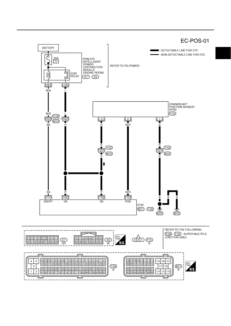
DTC P0335 CKP SENSOR (POS)
EC-1077
[VK45DE]
C
D
E
F
G
H
I
J
K
L
M
A
EC
Wiring Diagram
NBS005GH
TBWT1027E
|
|
|
DTC P0335 CKP SENSOR (POS) EC-1077 [VK45DE] C D E F G H I J K L M A EC Wiring Diagram NBS005GH TBWT1027E |