Infiniti M35/M45 Y50. Manual - part 182
DIAGNOSIS SYSTEM
AV-105
[WITHOUT MOBILE ENTERTAINMENT SYSTEM]
C
D
E
F
G
H
I
J
L
M
A
B
AV
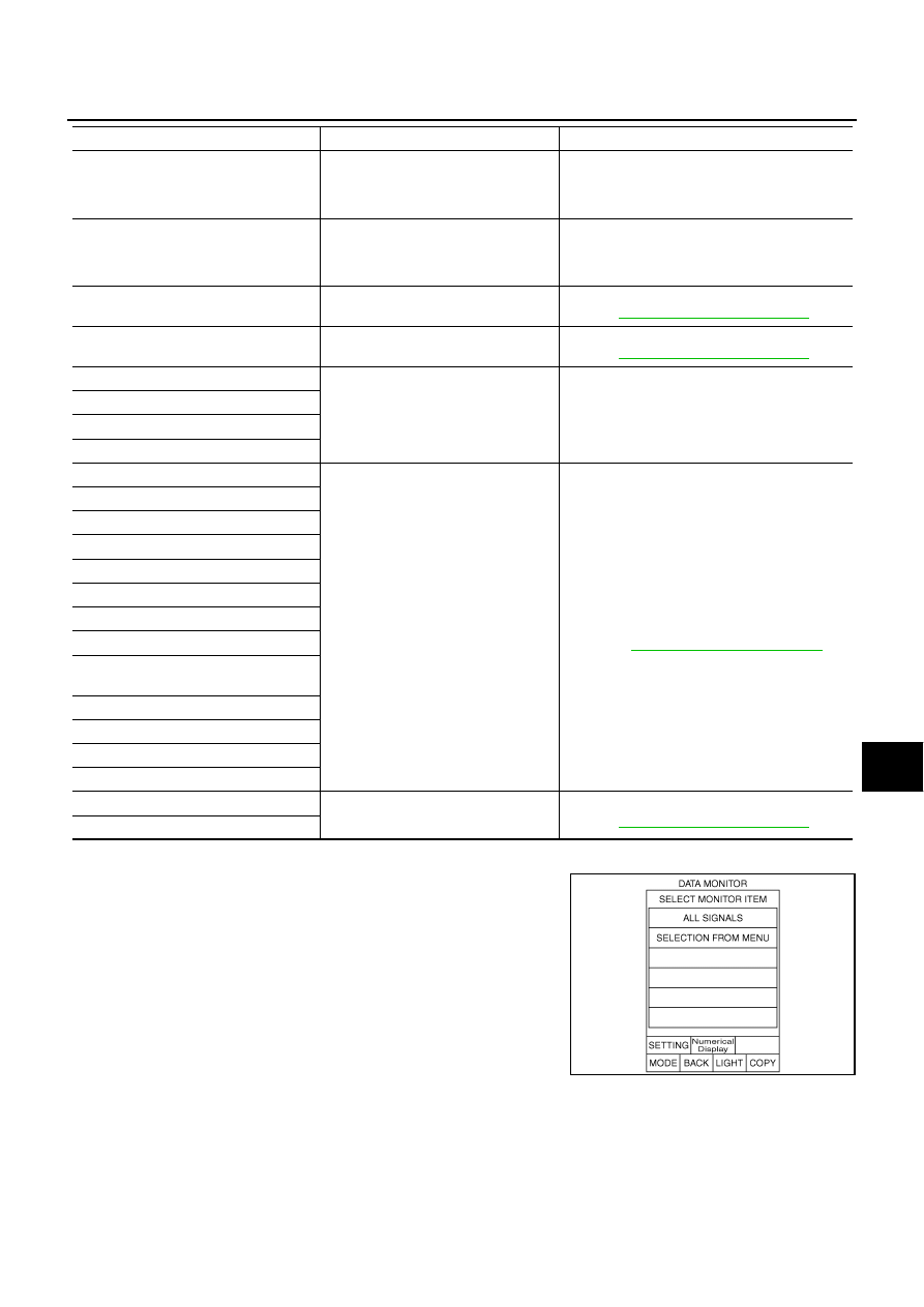
DATA MONITOR
When “DATA MONITOR” is selected, “ALL SIGNALS” and “SELEC-
TION FROM MENU” are displayed.
GPS ANTENNA CONN [U1244]
GPS antenna connection malfunction
is detected
●
GPS antenna feeder
●
GPS antenna
●
NAVI control unit
CAMERA CONT CONN [U1250]
Camera and connection recognition
signal circuit malfunction is detected
●
Camera-connection recognition signal circuit
●
Camera control unit
●
AV (NAVI) control unit
Cont Unit FLASH-ROM [U1200]
AV (NAVI) control unit malfunction is
detected
Replace AV (NAVI) control unit
Refer to
AV-131, "AV (NAVI) Control Unit"
GYRO NO CONN [U1201]
NAVI control unit malfunction is
detected
Replace NAVI control unit
Refer to
AV-131, "AV (NAVI) Control Unit"
GPS COMM [U1204]
GPS malfunction is detected
If the symptoms such as the GPS receipt mal-
function occur, intermittent malfunction caused
by strong radio interference may be detected.
If the malfunction always occurs, replace NAVI
control unit.
GPS ROM [U1205]
GPS RAM [U1206]
GPS RTC [U1207]
DVD-ROM COMM [U1208]
●
Malfunction is detected on DVD-
ROM drive pickup lens in NAVI con-
trol unit
●
There is dirt and damage on the map
disc
●
Map disc
●
NAVI control unit
Refer to
AV-131, "AV (NAVI) Control Unit"
DVD-ROM READ [U1209]
DVD-ROM DISC [U120A]
DVD-ROM MECHA DETECT [U120C]
DVD-ROM DRIVE MECHA [U120D]
DVD-ROM FOCUS [U120E]
DVD-ROM TOC [U120F]
DVD-ROM SEEK [U1210]
DVD-ROM ERR CORRECTION
[U1211]
DVD-ROM DATA FORWARD [U1212]
DVD-ROM DATA [U1213]
DVD-ROM TIMEOUT [U1214]
DVD-ROM LOAD [U1215]
CAN CONT [U1216]
AV (NAVI) control unit malfunction is
detected
Replace AV (NAVI) control unit
Refer to
AV-131, "AV (NAVI) Control Unit"
BLUETOOTH CONN [U1217]
Error item
Description
Possible cause/Action to take
SKIB3675E