Infiniti M35/M45 Y50. Manual - part 102


  Index      Infiniti     Infiniti M35/M45 Y50 - service repair manual 2007 year


Search            copyright infringement  


Content   ..  100  101  102  103   ..


Infiniti M35/M45 Y50. Manual - part 102


REPAIR FOR COMPONENT PARTS

AT-331

D

E

F

G

H

I

J

K

L

M

A

B

AT

CAUTION:

If necessary, replace the input clutch assembly.

Front Carrier

Check for deformation, fatigue or damage.

CAUTION:

If necessary, replace the front carrier assembly.

Rear Internal Gear

Check for deformation, fatigue or damage.

CAUTION:

If necessary, replace the rear internal gear.

ASSEMBLY

1.

Install input clutch.

a.

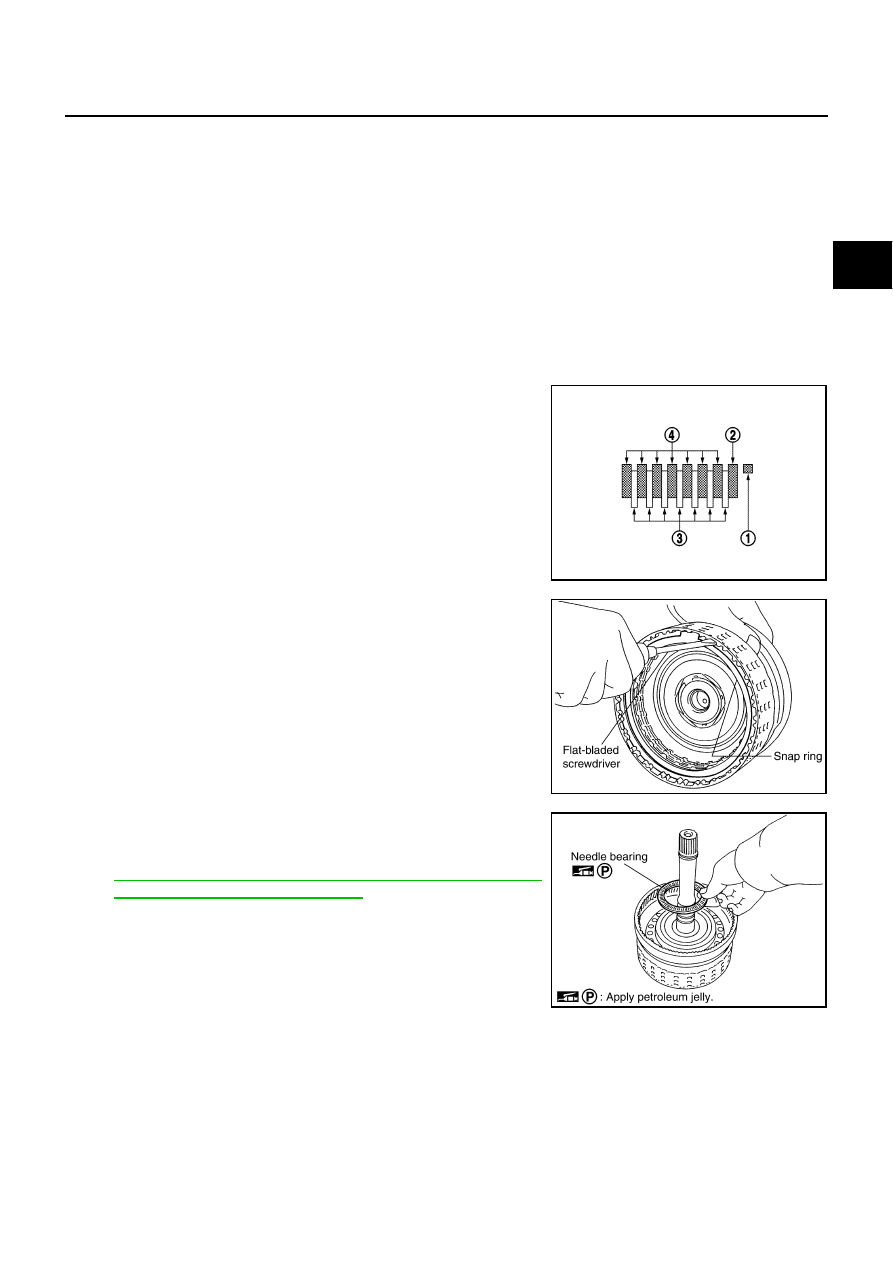
Install drive plates, driven plates and retaining plate in input
clutch drum.

Snap ring (1)

Retaining plate (2)

Drive plate (3)

Driven plate (4)

Drive plate/Driven plate: 7/7

CAUTION:

Take care with order of plates.

b.

Using a flat-bladed screwdriver, install snap ring in input clutch
drum.

c.

Install needle bearing in input clutch assembly.

CAUTION:

Take care with the direction of needle bearing. Refer to

AT-298, "Locations of Adjusting Shims, Needle Bearings,
Thrust Washers and Snap Rings"

 .

Apply petroleum jelly to needle bearing.

SCIA7133E

SCIA2864E

SCIA2853E

AT-332

REPAIR FOR COMPONENT PARTS

d.

Install O-ring and seal rings in input clutch assembly.

CAUTION:

Do not reuse O-ring and seal rings.

Apply ATF to O-ring.

Apply petroleum jelly to seal rings.

2.

Install front carrier assembly.

a.

Install snap ring to front carrier assembly.

CAUTION:

Do not expand snap ring excessively.

b.

Install needle bearing in front carrier assembly.

CAUTION:

Take care with the direction of needle bearing. Refer to

AT-298, "Locations of Adjusting Shims, Needle Bearings,
Thrust Washers and Snap Rings"

 .

Apply petroleum jelly to needle bearing.

c.

Install bearing race in front carrier assembly.

CAUTION:

Apply petroleum jelly to bearing race.

d.

Install front carrier assembly to input clutch assembly.

3.

Compress snap ring using 2 flat-bladed screwdrivers.

4.

Install front carrier assembly and input clutch assembly to rear
internal gear.

SCIA5235E

SCIA5476E

SCIA5233E

SCIA2847E

SCIA5339E

REPAIR FOR COMPONENT PARTS

AT-333

D

E

F

G

H

I

J

K

L

M

A

B

AT

Mid Sun Gear, Rear Sun Gear, High and Low Reverse Clutch Hub

NCS001R7

COMPONENTS

VQ35DE models

VK45DE models

SCIA7071E

1.

Needle bearing

2.

Bearing race

3.

Snap ring

4.

High and low reverse clutch hub

5.

Needle bearing

6.

Snap ring

7.

1st one-way clutch

8.

Rear sun gear

9.

Seal ring

10. Mid sun gear

Refer to GI section to make sure icons (symbol marks) in the figure. Refer to 

GI-11, "Components"

 .

SCIA7072E

1.

Needle bearing

2.

Bearing race

3.

Snap ring

4.

High and low reverse clutch hub

5.

Needle bearing

6.

Snap ring

7.

1st one-way clutch

8.

Rear sun gear

9.

Seal ring

10. Mid sun gear

Refer to GI section to make sure icons (symbol marks) in the figure. Refer to 

GI-11, "Components"

 .

AT-334

REPAIR FOR COMPONENT PARTS

DISASSEMBLY

1.

Remove needle bearing and bearing races from high and low reverse clutch hub.

VQ35DE models

VK45DE models

2.

Using a pair of snap ring pliers, remove snap ring from mid sun
gear assembly.

CAUTION:

Do not expand snap ring excessively.

3.

Remove high and low reverse clutch hub from mid sun gear
assembly.

SCIA2854E

SCIA5238E

SCIA2855E

SCIA2856E


Content   ..  100  101  102  103   ..