Infiniti M35/M45 Y50. Manual - part 53


  Index      Infiniti     Infiniti M35/M45 Y50 - service repair manual 2007 year


Search            copyright infringement  


Content   ..  51  52  53  54   ..


Infiniti M35/M45 Y50. Manual - part 53


DTC P1710 A/T FLUID TEMPERATURE SENSOR CIRCUIT

AT-135

D

E

F

G

H

I

J

K

L

M

A

B

AT

DTC P1710 A/T FLUID TEMPERATURE SENSOR CIRCUIT

PFP:31940

Description

NCS001MF

The A/T fluid temperature sensor detects the A/T fluid temperature and sends a signal to the TCM.

CONSULT-II Reference Value

NCS001MG

On Board Diagnosis Logic

NCS001MH

This is an OBD-II self-diagnostic item.

Diagnostic trouble code “P1710 (A/T), P0710 (ENGINE) ATF TEMP SEN/CIRC” with CONSULT-II or 10th
judgement flicker without CONSULT-II is detected when TCM receives an excessively low or high voltage
from the sensor.

Possible Cause

NCS001MI

Harness or connectors
(Sensor circuit is open or shorted.)

A/T fluid temperature sensors 1 and/or 2

DTC Confirmation Procedure

NCS001MJ

CAUTION:

Always drive vehicle at a safe speed.

NOTE:
If “DTC Confirmation Procedure” has been previously performed, always turn ignition switch OFF and
wait at least 10 seconds before performing the next test.
After the repair, perform the following procedure to confirm the malfunction is eliminated.

 WITH CONSULT-II

1.

Turn ignition switch ON.

2.

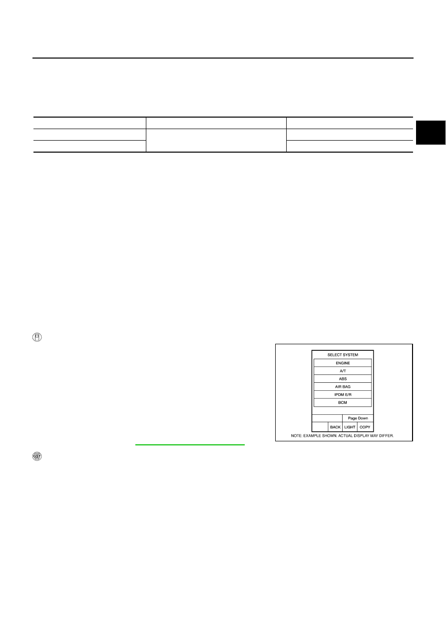
Select “SELECTION FROM MENU” in “DATA MONITOR” mode
for “A/T” with CONSULT-II and check monitor “VHCL/S SE-A/T”,
“ACCELE POSI” and “SLCT LVR POSI ”.

3.

Touch “START”.

4.

Start engine and maintain the following conditions for at least 10
minutes (Total). (It is not necessary to maintain continuously.)
VHCL/S SE-A/T: 10 km/h (6 MPH) or more
ACCELE POSI: More than 1.0/8
SLCT LVR POSI: “D” position 

5.

If DTC is detected, go to 

AT-137, "Diagnostic Procedure"

 .

 WITH GST

Follow the procedure “WITH CONSULT-II”.

Item name

Condition 

°

C (

°

F)

Display value (Approx.)

ATF TEMP SE 1

0 (32) - 20 (68) - 80 (176)

3.3 - 2.7 - 0.9 V

ATF TEMP SE 2

3.3 - 2.5 - 0.7 V

BCIA0030E

AT-136

DTC P1710 A/T FLUID TEMPERATURE SENSOR CIRCUIT

Wiring Diagram — AT — FTS

NCS001MK

TCWT0346E

DTC P1710 A/T FLUID TEMPERATURE SENSOR CIRCUIT

AT-137

D

E

F

G

H

I

J

K

L

M

A

B

AT

Diagnostic Procedure

NCS001ML

1. 

CHECK A/T FLUID TEMPERATURE SENSOR 1 SIGNAL

 With CONSULT-II

1.

Start engine.

2.

Select “ECU INPUT SIGNALS” in “DATA MONITOR” mode for
“A/T” with CONSULT-II.

3.

Read out the value of “ATF TEMP SE 1”.

OK or NG

OK >> GO 

TO 

2.

NG

>> GO TO 3.

2. 

CHECK A/T FLUID TEMPERATURE SENSOR 2 SIGNAL

 With CONSULT-II

1.

Start engine.

2.

Select “ECU INPUT SIGNALS” in “DATA MONITOR” mode for
“A/T” with CONSULT-II.

3.

Read out the value of “ATF TEMP SE 2”.

OK or NG

OK >> GO 

TO 

8.

NG

>> GO TO 5.

3. 

CHECK A/T FLUID TEMPERATURE SENSOR 1 

Check A/T fluid temperature sensor 1. Refer to 

AT-139, "A/T FLUID TEMPERATURE SENSOR 1"

 .

OK or NG

OK

>> GO TO 4.

NG

>> Replace the control valve with TCM. Refer to 

AT-236, "Control Valve With TCM and A/T Fluid

Temperature Sensor 2"

 .

4. 

CHECK SUB-HARNESS

1.

Disconnect park/neutral position switch connector and TCM connector.

2.

Check continuity between park/neutral position switch connector
terminals and TCM connector terminals.

3.

If OK, check harness for short to ground and short to power.

OK or NG

OK

>> GO TO 7.

NG

>> Replace open circuit or short to ground and short to power in harness or connectors.

Item name

Condition 

°

C (

°

F)

Display value (Approx.)

ATF TEMP SE 1

0 (32) - 20 (68) - 80 (176)

3.3 - 2.7 - 0.9 V

PCIA0039E

Item name

Condition 

°

C (

°

F)

Display value (Approx.)

ATF TEMP SE 2

0 (32) - 20 (68) - 80 (176)

3.3 - 2.5 - 0.7 V

PCIA0039E

Item

Connector

Terminal

Continuity

Park/neutral position switch 
connector

F505

6

Yes

TCM connector 

F503

19

Park/neutral position switch 
connector

F505

7

Yes

TCM connector 

F503

18

SCIA5461E

AT-138

DTC P1710 A/T FLUID TEMPERATURE SENSOR CIRCUIT

5. 

CHECK A/T FLUID TEMPERATURE SENSOR 2 

Check A/T fluid temperature sensor 2. Refer to 

AT-139, "A/T FLUID TEMPERATURE SENSOR 2"

 .

OK or NG

OK

>> GO TO 6.

NG

>> Replace the A/T fluid temperature sensor 2. Refer to 

AT-246, "A/T FLUID TEMPERATURE SEN-

SOR 2 REMOVAL AND INSTALLATION"

 .

6. 

CHECK TERMINAL CORD ASSEMBLY

1.

Disconnect A/T fluid temperature sensor 2 connector and TCM connector.

2.

Check continuity between A/T fluid temperature sensor 2 con-
nector terminals and TCM connector terminals.

3.

If OK, check harness for short to ground and short to power.

OK or NG

OK

>> GO TO 7.

NG

>> Replace open circuit or short to ground and short to power in harness or connectors.

7. 

CHECK TCM POWER SUPPLY AND GROUND CIRCUIT

1.

Check TCM power supply and ground circuit. Refer to 

AT-180, "MAIN POWER SUPPLY AND GROUND

CIRCUIT"

 .

2.

Reinstall any part removed.

OK or NG

OK

>> Replace the control valve with TCM. Refer to 

AT-236, "Control Valve With TCM and A/T Fluid

Temperature Sensor 2"

 .

NG

>> Repair or replace damaged parts.

8. 

CHECK DTC

Perform “DTC Confirmation Procedure”. Refer to 

AT-135, "DTC Confirmation Procedure"

 .

OK or NG

OK

>> INSPECTION END

NG

>> GO TO 1.

Item

 Connector

Terminal

Continuity

A/T fluid temperature sen-
sor 2 connector

F507

1

Yes

TCM connector 

F502

3

A/T fluid temperature sen-
sor 2 connector

F507

2

Yes

TCM connector 

F502

5

SCIA5462E


Content   ..  51  52  53  54   ..