Infiniti M35/M45 Y50. Manual - part 22


  Index      Infiniti     Infiniti M35/M45 Y50 - service repair manual 2007 year


Search            copyright infringement  


Content   ..  20  21  22  23   ..


Infiniti M35/M45 Y50. Manual - part 22


PREPARATION

AT-11

D

E

F

G

H

I

J

K

L

M

A

B

AT

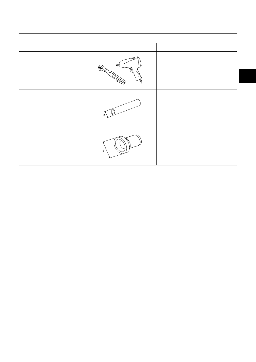
Commercial Service Tools

NCS001JH

Tool name

Description

Power tool

Loosening bolts and nuts

Drift
a: 22 mm (0.87 in) dia.

Installing manual shaft oil seals

Drift
a: 64 mm (2.52 in) dia.

Installing rear oil seal (AWD models)

PBIC0190E

NT083

SCIA5338E

AT-12

A/T FLUID

A/T FLUID

PFP:KLE40

Changing A/T Fluid

NCS001JI

1.

Warm up ATF.

2.

Stop engine.

3.

Loosen the level gauge bolt.

4.

Drain ATF from drain plug and refill with new ATF. Always refill
same volume with drained ATF.

To replace the ATF, pour in new ATF at the A/T fluid charging
pipe with the engine idling and at the same time drain the old
ATF from the radiator cooler hose return side.

When the color of the ATF coming out is about the same as
the color of the new ATF, the replacement is complete. The
amount of new ATF to use should be 30 to 50% increase of
the stipulated amount.

CAUTION:

Use only Genuine NISSAN Matic J ATF. Do not mix with other ATF.

Using ATF other than Genuine NISSAN Matic J ATF will cause deterioration in driveability and A/
T durability, and may damage the A/T, which is not covered by the warranty.

When filling ATF, take care not to scatter heat generating parts such as exhaust.

Do not reuse drain plug gasket.

5.

Run engine at idle speed for 5 minutes.

6.

Check A/T fluid level and condition. Refer to 

AT-13, "Checking A/T Fluid"

 . If ATF is still dirty, repeat step 2.

through 5.

7.

Install the removed A/T fluid level gauge into A/T fluid charging pipe.

8.

Tighten the level gauge bolt.

ATF:

Genuine NISSAN Matic J ATF

Fluid capacity:

10.3  (10-7/8 US qt, 9-1/8 lmp qt)

Drain plug

: 34 N·m (3.5 kg-m, 25 ft-lb)

Level gauge bolt

: 5.1 N·m (0.52 kg-m, 45 in-lb)

SCIA4896E

A/T FLUID

AT-13

D

E

F

G

H

I

J

K

L

M

A

B

AT

Checking A/T Fluid

NCS001JJ

1.

Warm up engine.

2.

Check for A/T fluid leakage.

3.

Loosen the level gauge bolt.

4.

Before driving, A/T fluid level can be checked at A/T fluid tem-
peratures of 30 to 50

°

C (86 to 122

°

F) using “COLD” range on A/

T fluid level gauge as follows.

a.

Park vehicle on level surface and set parking brake.

b.

Start engine and move selector lever through each gear posi-
tion. Leave selector lever in “P” position.

c.

Check A/T fluid level with engine idling.

d.

Remove A/T fluid level gauge and wipe clean with lint-free
paper.

CAUTION:

When wiping away the A/T fluid level gauge, always use
lint-free paper, not a cloth one.

e.

Re-insert A/T fluid level gauge into A/T fluid charging pipe as far as it will go.

CAUTION:

To check A/T fluid level, insert the A/T fluid level gauge until the cap contacts the end of the A/T
fluid charging pipe, with the A/T fluid level gauge reversed from the normal attachment conditions.

f.

Remove A/T fluid level gauge and note reading. If reading is at low side of range, add ATF to the A/T fluid
charging pipe.

CAUTION:

Do not overfill.

5.

Drive vehicle for approximately 5 minutes in urban areas.

6.

Make the A/T fluid temperature approximately 65

°

C (149

°

F).

NOTE:
A/T fluid level will be greatly affected by temperature as shown in figure. Therefore, be certain to
perform operation while checking data with CONSULT-II.

a.

Connect CONSULT-II to data link connector. Refer to 

GI-38, "CONSULT-II Start Procedure"

 .

b.

Select “MAIN SIGNALS” in “DATA MONITOR” mode for “A/T” with CONSULT-II.

c.

Read out the value of “ATF TEMP 1”.

7.

Re-check A/T fluid level at A/T fluid temperatures of approximately 65

°

C (149

°

F) using “HOT” range on A/

T fluid level gauge.

SCIA7120E

SLIA0016E

AT-14

A/T FLUID

CAUTION:

When wiping away the A/T fluid level gauge, always use lint-free paper, not a cloth one.

To check A/T fluid level, insert the A/T fluid level gauge
until the cap contacts the end of the A/T fluid charging
pipe, with the A/T fluid level gauge reversed from the nor-
mal attachment conditions as shown.

8.

Check A/T fluid condition.

If ATF is very dark or smells burned, check operation of A/T.
Flush cooling system after repair of A/T.

If A/T fluid contains frictional material (clutches, bands, etc.),
replace radiator and flush cooler line using cleaning solvent
and compressed air after repair of A/T. Refer to 

CO-14,

"RADIATOR"

  (for VQ35DE engine), 

CO-43, "RADIATOR"

(for VK45DE engine) an

AT-14, "A/T Fluid Cooler Cleaning"

 .

9.

Install the removed A/T fluid level gauge in the A/T fluid charging
pipe.

10. Tighten level gauge bolt.

A/T Fluid Cooler Cleaning

NCS001JK

Whenever an A/T is replaced, the A/T fluid cooler mounted in the radiator must be inspected and cleaned.
Metal debris and friction material, if present, can become trapped in the A/T fluid cooler. This debris can con-
taminate the newly serviced A/T or, in severe cases, can block or restrict the flow of ATF. In either case, mal-
function of the newly serviced A/T may result.
Debris, if present, may build up as ATF enters the cooler inlet. It will be necessary to back flush the cooler
through the cooler outlet in order to flush out any built up debris.

A/T FLUID COOLER CLEANING PROCEDURE

1.

Position an oil pan under the A/T inlet and outlet cooler hoses.

2.

Identify the inlet and outlet fluid cooler hoses.

3.

Disconnect the A/T fluid cooler inlet and outlet rubber hoses
from the steel cooler tubes or bypass valve.

NOTE:
Replace the cooler hoses if rubber material from the hose
remains on the tube fitting.

4.

Allow any ATF that remains in the cooler hoses to drain into the
oil pan.

Level gauge bolt

: 5.1 N·m (0.52 kg-m, 45 in-lb)

SCIA2899E

SCIA4896E

SCIA3830E


Content   ..  20  21  22  23   ..