Infiniti M35/M45 Y50. Manual - part 5


  Index      Infiniti     Infiniti M35/M45 Y50 - service repair manual 2007 year


Search            copyright infringement  


Content   ..  3  4  5  6   ..


Infiniti M35/M45 Y50. Manual - part 5


ACTION TEST

ACS-13

[ICC]

C

D

E

F

G

H

I

J

L

M

A

B

ACS

Check For MAIN Switch

1.

Start engine. Then, check if the following operations are per-
formed correctly.

2.

Vehicle-to-vehicle distance control mode is displayed in combi-
nation meter and “CRUISE” is illuminated when MAIN switch is
pressed “ON” for less than 1.5 seconds and ready for operation.
The illumination goes off when MAIN switch is turned to OFF.

3.

“CRUISE” illumination and dot matrix LCD go off when the igni-
tion switch is turned to OFF while MAIN switch is ON (“CRUISE”
illumination is ON and vehicle-to-vehicle distance control mode
is ready for operation).

Check For RESUME/ACCELERATE, SET/COAST, CANCEL Switches

1.

Check if RESUME/ACCELERATE, SET/COAST, CANCEL switches are operated smoothly.

2.

Check if switches come up as hand is released from the switches.

Check For Distance Switch

1.

Start engine.

2.

Press the MAIN switch for less than 1.5 seconds.

3.

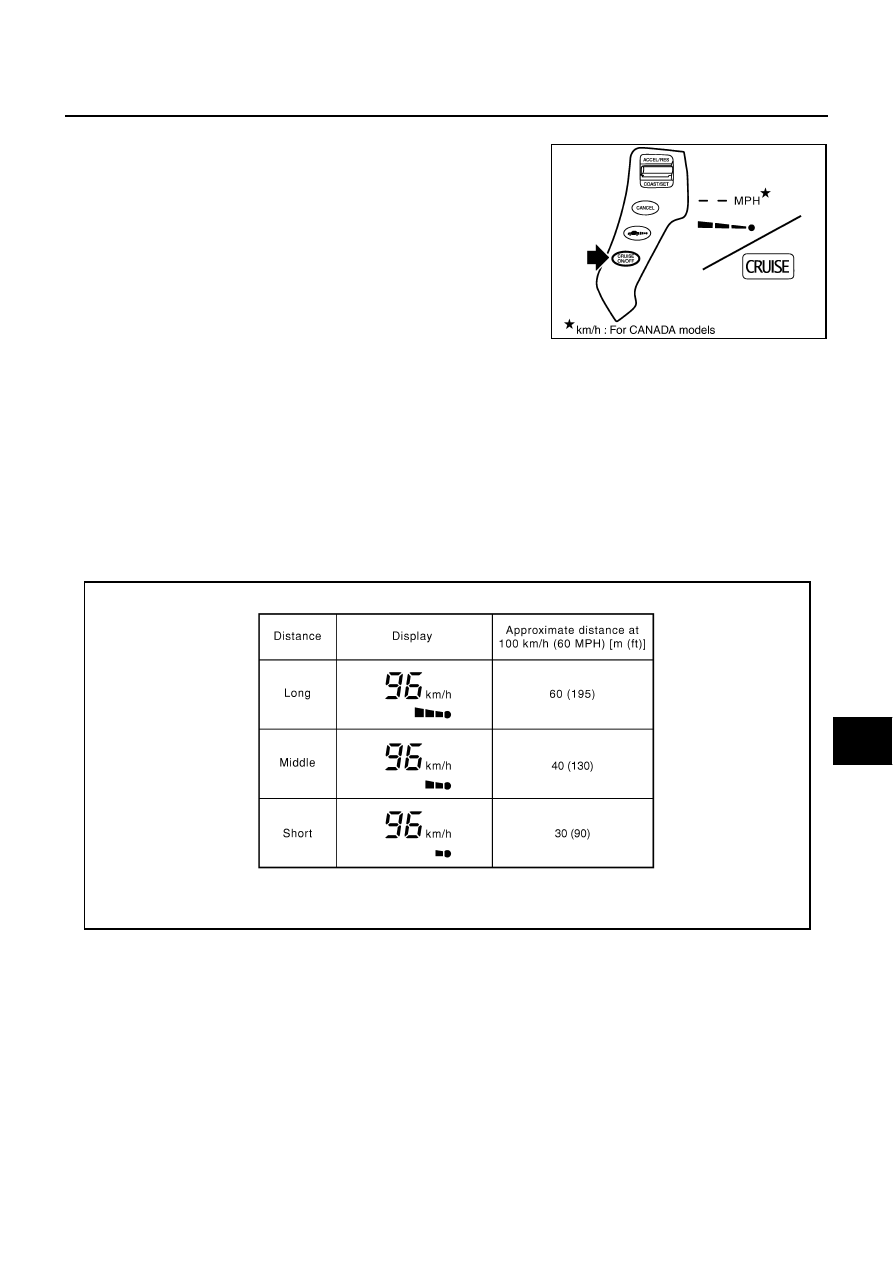
Press the DISTANCE switch.

4.

 Check if the set distance indicator changes display in order of:
(Long)

(Middle)

(Short).

NOTE:
 The set distance indicator shows (Long) immediately after the engine starts.

CONVENTIONAL (FIXED SPEED) CRUISE CONTROL MODE
Set Checking

1.

Press the MAIN switch for more than 1.5 seconds.

2.

Drive the vehicle between 40 km/h (25 MPH) and 144 km/h (90 MPH).

3.

Push down the SET/COAST switch.

4.

Confirm that the desired speed is set as hand is released from the SET/COAST switch.

NOTE:
The set vehicle speed is not displayed on the dot matrix LCD in the combination meter.

PKIB8348E

SKIB8746E

ACS-14

[ICC]

ACTION TEST

Check For Increase Of Cruising Speed

1.

Set the conventional (fixed speed) cruise control mode at desired speed.

2.

Check if the set speed increases by 1.6 km/h (1 MPH) as RESUME/ACCELERATE switch is pushed up.

NOTE:

If the RESUME/ACCELERATE switch is kept pushing up during cruise control driving, the vehicle speed
increases until the switch is released.

The maximum set speed is 144 km/h (90 MPH).

Check For Decrease Of Cruising Speed

1.

Set the conventional (fixed speed) cruise control mode at desired speed.

2.

Check if the set speed decreases by 1.6 km/h (1 MPH) as SET/COAST switch is pushed down.

NOTE:

Conventional (fixed speed) cruise control mode is automatically cancelled when the driving speed lowers
to 32 km/h (20 MPH).

The lowest set speed is 40 km/h (25 MPH).

Check For Cancellation Of Conventional (Fixed Speed) Cruise Control Mode (Normal Driving 
Condition) In The Following Cases:

Refer to 

ACS-12, "Check For Cancellation Of Vehicle-To-Vehicle Distance Control Mode (Normal Driving Con-

dition) In The Following Cases:"

 .

Check For Restoring Speed That Is Set By Conventional (Fixed Speed) Cruise Control Mode 
Before ICC Cancellation

Refer to 

ACS-12, "Check For Restoring Speed That Is Set By Vehicle-To-Vehicle Distance Control Mode

Before Cancellation"

 .

Check For MAIN Switch

1.

Start engine. Then, check if the following operations are per-
formed correctly.

2.

“CRUISE” lamp illuminates and dot matrix LCD goes off when
MAIN switch is pressed “ON” for more than 1.5 seconds, and
then ready for operation. The illumination goes off when MAIN
switch is turned to OFF.

3.

“CRUISE” illumination go off when the ignition switch is turned to
OFF while MAIN switch is ON.

Check For RESUME/ACCELERATE, SET/COAST, CANCEL Switches

1.

Check if RESUME/ACCELERATE, SET/COAST, CANCEL switches are operated smoothly.

2.

Check if switches come up as hand is released from the switches.

PKIB5342J

LASER BEAM AIMING ADJUSTMENT

ACS-15

[ICC]

C

D

E

F

G

H

I

J

L

M

A

B

ACS

LASER BEAM AIMING ADJUSTMENT

PFP:00026

Outline

NKS004CM

Adjust the laser beam aiming every time the ICC sensor integrated unit is removed or installed.

CAUTION:

Adjust laser beam aiming at a horizontal place as far as 12 m (39 ft) forward the vehicle can be
seen.

Adjust laser beam aiming 5 seconds after starting engine.

Never view ICC sensor integrated unit body window directly during laser beam aiming adjustment.

Follow the CONSULT-II when adjusting the laser beam aiming (laser beam aiming adjustment can-
not be operated without CONSULT-II).

Never ride on vehicle during laser beam aiming adjustment.

Idle and turn headlamps OFF during laser beam aiming adjustment.

Preparation

NKS004CN

Adjust the tire pressure to the specified value.

See that there is no load in the vehicle. 

Coolant, engine oil filled up to correct level and full fuel tank.

Shift the gear into “P” position and release the parking brake.

Clean the ICC sensor integrated unit with a soft cloth.

Remove the front bumper grille. Refer to 

EI-13, "Removal and

Installation of Front Bumper Grille"

 .

Outline of Adjustment Procedure

NKS004CO

1.

Set up the ICC target board [KV99110100 (J-45718)].

2.

Adjust the sensor following the procedure on CONSULT-II. (Turn manually the screw for up-down position
adjustment. ICC sensor integrated unit automatically adjust the right-left position.)

Setting the ICC Target Board

NKS004CP

Accurate ICC target board setting is required for the laser beam aiming adjustment.

CAUTION:

ICC system does not function normally if laser beam aiming is not accurate.

ADJUSTING HEIGHT OF THE TARGET

1.

Attach a triangle scale at 28 mm (1.10 in) below the center.

PKIB8350E

PKIB8351E

ACS-16

[ICC]

LASER BEAM AIMING ADJUSTMENT

2.

Adjust the height of the target board with aligning the upside tip
of the triangle scale with the center of laser beam axis.

NOTE:
The center of laser beam axis is located at 92 mm (3.62 in) from
the right edge and 22 mm (0.87 in) from the top of the ICC sen-
sor integrated unit from a front view of vehicle.

ADJUSTING THE RIGHT-LEFT POSITION OF THE TARGET

1.

Attach a scale [at least 350 mm (14 in) or longer] or stick as
shown in the figure.

2.

Suspend a thread with weight on the tip of the thread to 266 mm
 (10.47 in) right side of the target board from the center of the
target board on top.

SETTING THE TARGET

1.

Suspend a thread with weight on tip to splice the center of the front and rear bumpers. Then, mark the
center point on the ground as each weight points.

2.

Link the front and rear bumpers center points marked on the ground, and mark a point 3.9 m (12.8 ft)
ahead of the front bumper, on the extended line of the previous link line of the bumper center points.
Then, adjust the position of the target board so that the weight come on the top of the marked point [3.9 m
(12.8 ft) ahead of the front bumper] and face to the vehicle.

PKIB4486J

PKIB8352E

PKIB8353E

PKIB8354E


Content   ..  3  4  5  6   ..